L NAPCO Security Systems
X GEM-X255 Programming Instructions
Page 53
WI1092E 10/05
EXTERNAL RELAY CONTROL
EXTERNAL RELAY CONTROL / RELAYS 79-96 (ADDRESS 3856-3873 & 3112-3183)
ADDRESS 3856 & 3112-3115 (RELAY/entry 79)
3856 3112 3113 3114 3115
L R L R L R L R
ADDRESS 3857 & 3116-3119 (RELAY/entry 80)
3857 3116 3117 3118 3119
L R L R L R L R
ADDRESS 3858 & 3120-3123 (RELAY/entry 81)
3858 3120 3121 3122 3123
L R L R L R L R
ADDRESS 3859 & 3124-3127 (RELAY/entry 82)
3859 3124 3125 3126 3127
L R L R L R L R
ADDRESS 3860 & 3128-3131 (RELAY/entry 83)
3860 3128 3129 3130 3131
L R L R L R L R
ADDRESS 3861 & 3132-3135 (RELAY/entry 84)
3861 3132 3133 3134 3135
L R L R L R L R
ADDRESS 3862 & 3136-3139 (RELAY/entry 85)
3862 3136 3137 3138 3139
L R L R L R L R
ADDRESS 3863 & 3140-3143 (RELAY/entry 86)
3863 3140 3141 3142 3143
L R L R L R L R
ADDRESS 3864 & 3144-3147 (RELAY/entry 87)
3864 3144 3145 3146 3147
L R L R L R L R
ADDRESS 3865 & 3148-3151 (RELAY/entry 88)
3865 3148 3149 3150 3151
L R L R L R L R
ADDRESS 3866 & 3152-3155 (RELAY entry 89)
3866 3152 3153 3154 3155
L R L R L R L R
ADDRESS 3867 & 3156-3159 (RELAY/entry 90)
3867 3156 3157 3158 3159
L R L R L R L R
ADDRESS 3868 & 3160-3163 (RELAY/entry 91)
3868 3160 3161 3162 3163
L R L R L R L R
ADDRESS 3869 & 3164-3167 (RELAY/entry 92)
3869 3164 3165 3166 3167
L R L R L R L R
ADDRESS 3870 & 3168-3171 (RELAY/entry 93)
3870 3168 3169 3170 3171
L R L R L R L R
ADDRESS 3871 & 3172-3175 (RELAY/entry 94)
3871 3172 3173 3174 3175
L R L R L R L R
ADDRESS 3872 & 3176-3179 (RELAY/entry 95)
3872 3176 3177 3178 3179
L R L R L R L R
ADDRESS 3873 & 3180-3183 (RELAY/entry 96)
3873 3180 3181 3182 3183
L R L R L R L R
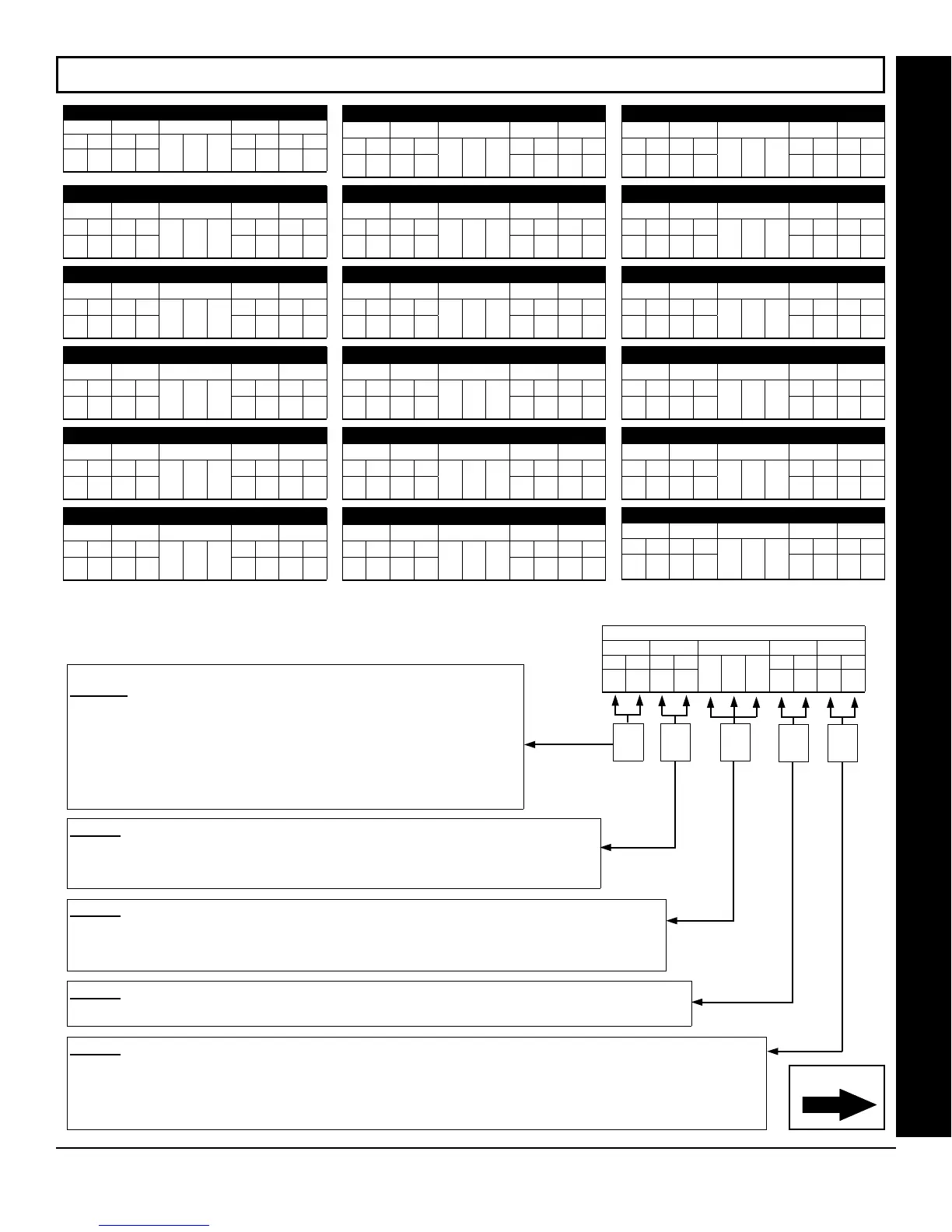
STEP 2: AREA OPTIONS: Each relay/entry can be assigned to Area 1-8 or all areas.
Select the area from Table 2 (shown on next page); enter in corresponding left and right digit
address locations.
RELAY EVENT OPTIONS
RELAY # AREA Timeout Event ID COND.
L R L R
L R L R
(•)
(•)
To program, follow the 5 steps below:
STEP 1: RELAY # OPTIONS: Each relay/entry can be assigned to any of the
96 available external relays from Relay Module RM3008. Multiple entries can
drive the same External Relay.
Select the relay number from Table 1 (shown on next page); enter in
corresponding left and right digit address locations.
Note: Entries 01-96 correspond to relays 1 through 96. If entries are zero, zero
(00), then relay number is identical to the relay/entry address table number, in
the selected address table(s) above.
STEP 3: TIMEOUTS: Each relay event can be assigned a timeout depending on Alarm Type option.
If Alarm Type is selected for timeout in minutes or seconds, enter the 3-digit timeout duration in corre-
sponding address location. To choose seconds or minutes, see step 5A below. 254 is maximum entry.
Continued
STEP 4: EVENT ID CODES: Each relay event can be assigned any of the available event IDs from the table.
Select 2-digit Event ID from Table 4 (see page 55); enter in corresponding address locations (left and right digit).
STEP 5: RELAY EVENT CONDITION OPTIONS: Each relay event can be assigned an alarm type; and an activation
condition; also, select a timeout type for each.
5A. Select Alarm Type and Timeout Type from Table 5A (see page 56); enter in corresponding address location (left digit).
NOTE: Select Timeout from Step 3.
5B. Select Activation from from Table 5B (see page 56); enter in corresponding address location (right digit).
Step
4
Step
5
[Default = blank (•) blank (•) from address 3778-3873 & 2800-3183]
Step
1
Step
2
Step
3