X GEM-X255 Programming Instructions
L NAPCO Security Systems
Page 54
WI1092E 10/05
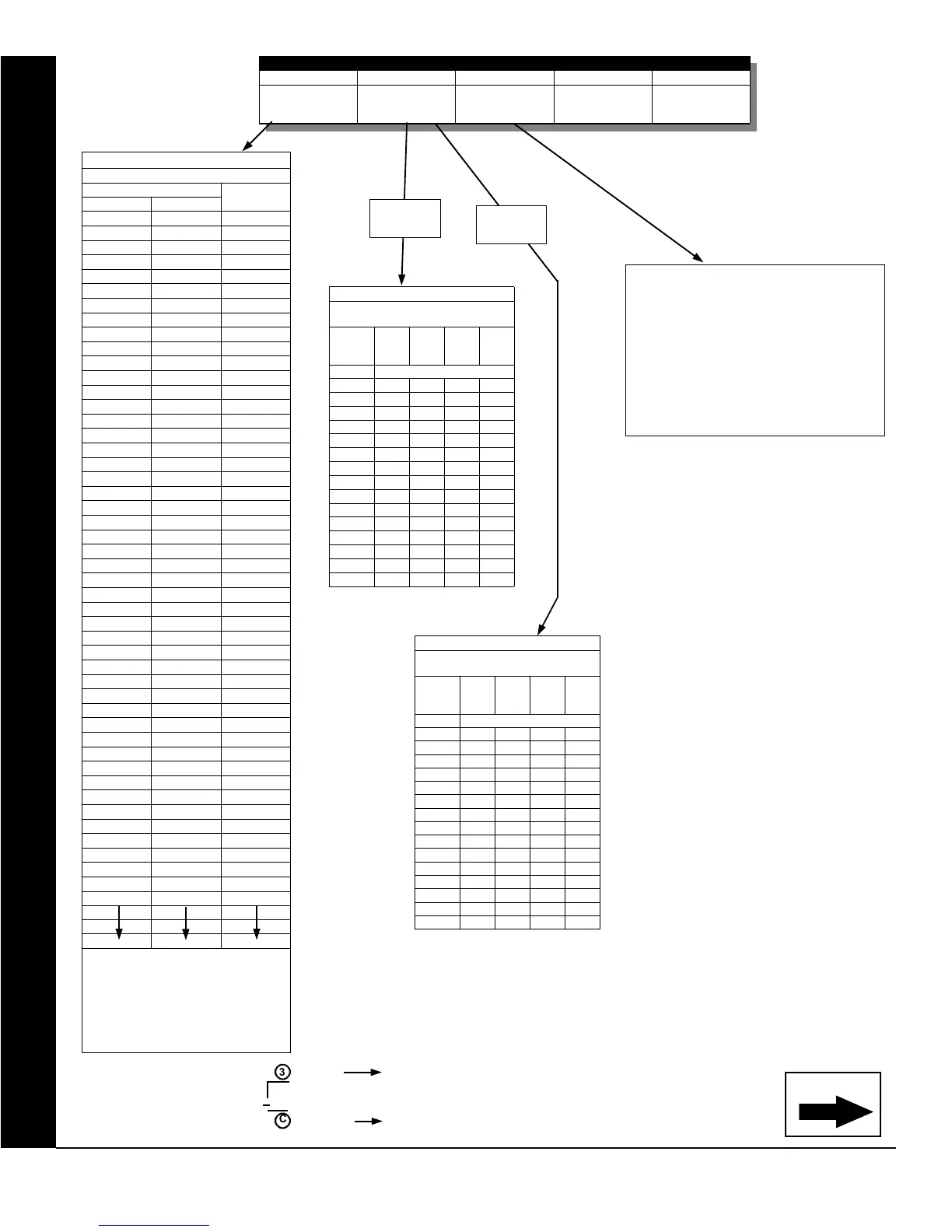
EXTERNAL RELAY CONTROL
For a desired relay not listed:
A. Choose a desired relay, ex: 60
B. Divide it by 16
3 Quotient Left Digit
16 60
48
C Remainder Right Digit
TABLE 2 (AREAS 5-8)
AREAS CONTROLLING RELAY
SHUTOFF ON DISARM
LEFT
DATA
ENTRY
AREA
8
AREA
7
AREA
6
AREA
5
blank (•) NONE
1 Y
2 Y
3 Y Y
4 Y
5 Y Y
6 Y Y
7 Y Y Y
8 Y
9 Y Y
0 Y Y
B Y Y Y
C Y Y
D Y Y Y
E Y Y Y
F Y Y Y Y
Note: “Y” indicates option is enabled.
TABLE 2 (AREAS 1-4)
RIGHT
DATA
ENTRY
AREA
4
AREA
3
AREA
2
AREA
1
blank (•) NONE
1 Y
2 Y
3 Y Y
4 Y
5 Y Y
6 Y Y
7 Y Y Y
8 Y
9 Y Y
0 Y Y
B Y Y Y
C Y Y
D Y Y Y
E Y Y Y
F Y Y Y Y
Note: “Y” indicates option is enabled.
AREAS CONTROLLING RELAY
SHUTOFF ON DISARM
TABLE 1
RELAY MAPPING
DATA ENTRIES
RELAY #
LEFT RIGHT
blank (•) blank (•) None *
blank (•) 1 1
blank (•) 2 2
blank (•) 3 3
blank (•) 4 4
blank (•) 5 5
blank (•) 6 6
blank (•) 7 7
blank (•) 8 8
blank (•) 9 9
blank (•) 0 10
blank (•) B 11
blank (•) C 12
blank (•) D 13
blank (•) E 14
blank (•) F 15
1 blank (•) 16
1 1 17
1 2 18
1 3 19
1 4 20
1 5 21
1 6 22
1 7 23
1 8 24
1 9 25
1 0 26
1 B 27
1 C 28
1 D 29
1 E 30
1 F 31
2 blank (•) 32
2 1 33
2 2 34
2 3 35
2 4 36
2 5 37
2 6 38
2 7 39
2 8 40
2 9 41
2 0 42
2 B 43
2 C 44
2 D 45
2 E 46
2 F 47
6 blank (•) 96
* Note: [blank (•) blank (•)] option affects the
relay with the same entry number. All other
options affect the relay number specified. Ex:
Suppose Relay/Entry 1 is mapped to External
Relay 1 and Relay/Entry 2 is mapped to
External Relay 24. The data entries are as
follows: Address 3778 = [blank (•) blank (•)] and
Address 3779 = [1C].
RELAY EVENT OPTIONS
RELAY # AREA TIMEOUT EVENT ID COND.
See
Table 1 below
See
Table 2 below
See
Table 3 below
See
Table 4 on page 55
See
Tables 5A & 5B on
page 56
Areas
1-4
Continued
Areas
5-8
TIMEOUTS: Each relay event can be
assigned a timeout depending on Alarm Type
option.
If Alarm Type is selected for timeout in
minutes or seconds, enter the 3-digit
time-
out duration
in corresponding address
location. To choose seconds or minutes,
see step 5A on page 56. Maximum entry
is 254.

 Loading...


