X GEM-X255 Programming Instructions
L NAPCO Security Systems
Page 56
WI1092E 10/05
EXTERNAL RELAY CONTROL
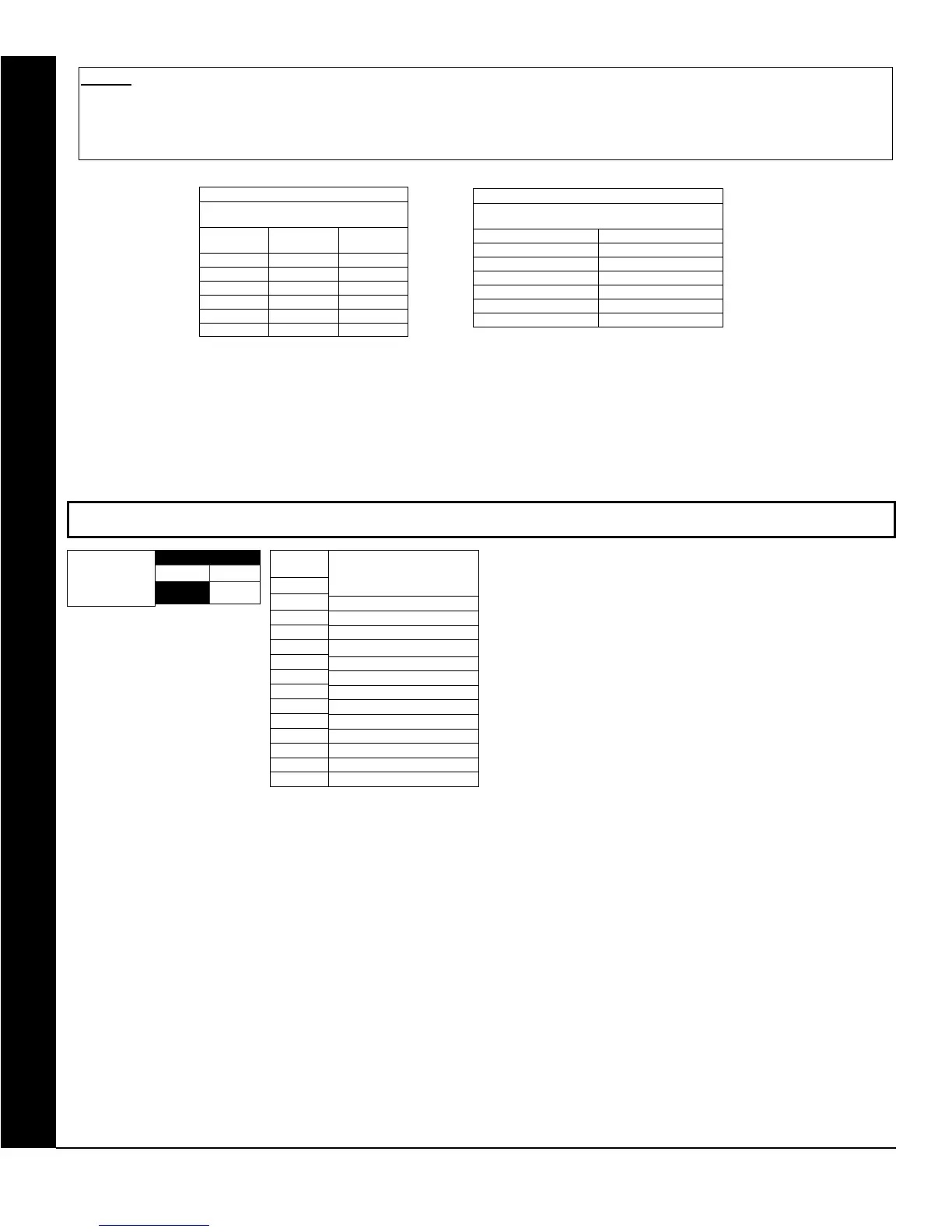
NUMBER OF RELAY BOARD MODULES (ADDRESS 3777)
[Default = blank (•) blank (•)]
LEFT RIGHT
blank (•)
ADDRESS 3777
Number of Relay
Board Modules
DATA
ENTRIES
RIGHT
blank (•)
1
2
3
4
5
6
7
8
9
0
B
C
Relay Board Module(s)
None
1
2
3
4
5
6
7
8
9
10
11
12
RELAY BOARD MODULES: Up to 12 External Relay Board
Modules (RM3008) may be programmed.
1. Select the number of relay modules from the table
shown.
2. Enter in corresponding right digit address location
shown (left digit is not used).
STEP 5: RELAY EVENT CONDITION OPTIONS: Each relay event can be assigned an alarm type; and an activation condition; also, select a
timeout type for each.
5A. Select Alarm Type and Timeout Type from Table 5A (below); enter in corresponding address location (left digit). NOTE: Select Timeout from
Step 3.
5B. Select Activation from from Table 5B (below); enter in corresponding address location (right digit).
TABLE 5A
RELAY EVENT
ALARM TYPE OPTIONS
LEFT DATA
ENTRIES
ALARM
TYPE
TIMEOUT
TYPE
blank (•) Burglary Minutes
1 Fire Minutes
4 Day Zone Minutes
8 Burglary Seconds
9 Fire Seconds
C Day Zone Seconds
TABLE 5B
RELAY EVENT
ACTIVATION CONDITIONS
RIGHT DATA ENTRIES OPTIONS
1 Alarm
2 Restore
3 Trouble
4 Trouble Restore
5 Follows Open Zone
6 Follows Shorted Zone