Page | 30
Selecting Composite + Y/C sends composite video output to the second BNC connector for the
corresponding output row (labeled Y), and Y/C to the third and fourth connectors, which are
labeled Pb and Pr, respectively.
You’ll notice output Proc Amp (color) controls below in each output tab as well, along with
individual output Audio level sliders.
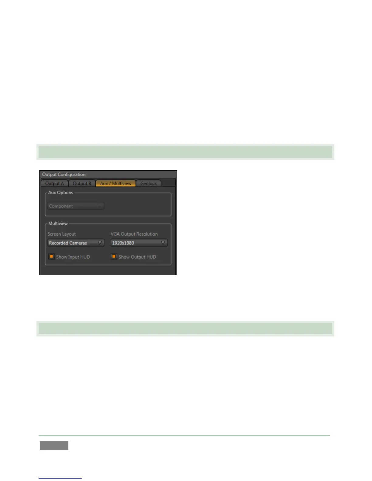
The third tab is labeled Aux/Multiview (3Play™ 820) or simply Multiview (3Play™ 425).
3.8 CONFIGURE MULTIVIEW OUTPUT
We’ll just discuss the Multiview control group
here (see Section 7.1.2 for a more thorough
examination). The Multiview output commonly
serves supplemental control room monitoring
needs, though other possibilities exist, too.
The Screen Layout options determine what the
Multiview output displays. Use VGA Output
Resolution to select a suitable resolution for the
device attached to the Multiview connector (if
any).
Make appropriate selections for your environment in this panel, and then click Close.
3.9 CONFIGURE GENLOCK
1. Click the Genlock tab in the Output Configuration panel.
2. The default Reference Type in the Genlock settings is SD (Bi-level), as this is currently the
most common reference signal type. However, if you supply an HD reference signal to
the Genlock input, you may want to change the setting to HD (Tri-level).