NIBE FIGHTER 1250
LE
K
LEK
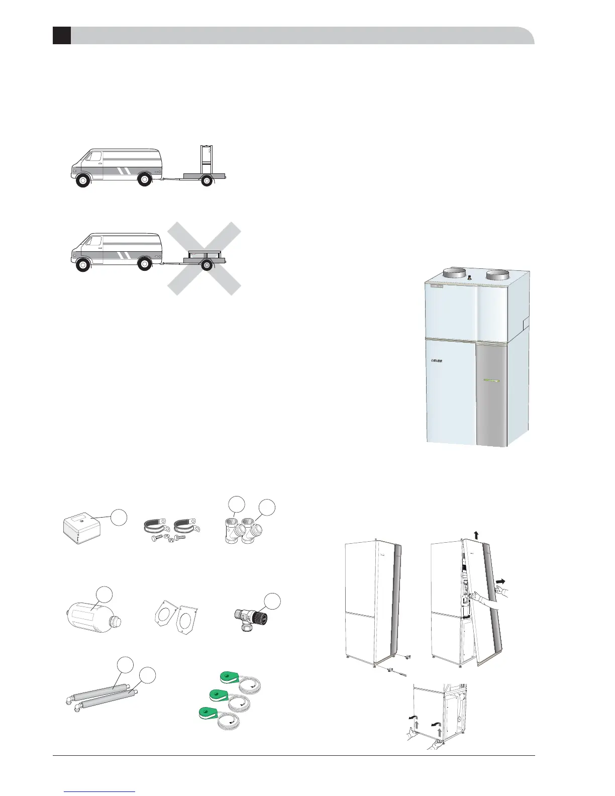
The FIGHTER 1250 must be transported and stored upright
and dry. FIGHTER 1250 may be carefully laid on its back
when being moved into a building.
Location
Place the heat pump:
on a fi rm base, preferably on a concrete fl oor or foun-
dation.
Install FIGHTER 1250 with its back to an outside wall,
ideally in a room where noise does not matter. If this
is not possible, avoid placing it against a wall behind a
bedroom or other room where noise may be a problem.
Wherever the unit is located, walls to sound sensitive
rooms should be fi tted with sound insulation.
Route pipes so they are not fi xed to an internal wall
that backs on to a bedroom or living room.
In addition to the actual heat pump, components are
enclosed on delivery
In a bag on top of the heat pump there are:
Outside sensor
Clips for connecting pipe brine
Particle fi lter
Level vessel with safety valve
Cover plates, brine
Connecting pipe brine, with insulation
Current transformers
Installation and Maintenance Instruction
A distance of 800 mm is
needed in front of FIGHTER
1250 and leave 400 mm of
space free to the right and
left of the heat pump for
servicing.
When FLM is fi tted on
FIGHTER 1250 the distance
to the wall should be at least
50 mm.
Service area
Level vessel
Particle fi lter
Cover plates,
brine
Outside sensor
LE
K
4
5
85
63
81
52
15
(Component numbering, see section F “List of components”)
LEK
Front cover
1. Remove the screws from the lower edge of the front
cover.
2. Lift the cover up and out.
LEK
FLM
Safety valve