NIBE FIGHTER 1250
B
Connecting the brine
When dimensioning the collector, consideration must
be given to the geographical location, type of rock and
ground and the degree of coverage provided by the heat
pump.
When installing the collector hose ensure it rises con-
stantly towards the heat pump to avoid air pockets. If
this is not possible, install high points to vent the air.
All brine lines must be insulated.
The level vessel (NK) must be installed as the highest
point in the brine system and on the incoming pipe be-
fore the brine pump.
The accompanying safety valve (SÄV) must be installed
under the level vessel as illustrated. The overfl ow pipe
from the safety valve must be routed enclosed along
its entire length to prevent water pockets and be frost
proof.
Note that condensation may drip from the level ves-
sel. Position the vessel so that this does not harm other
equipment.
As the temperature of the brine system can fall below 0
°C it must be protected against freezing down to -15 °C.
One litre of ready mixed brine per metre of collector hose
(applies when using PEM-hose 40 x 2.4 PN 6.3) is used as a
guide value when making the volume calculation.
Details of the antifreeze used must be shown on the
level vessel.
The brine system may be connected from the left or
from the right.
The lower side panels are swapped over to suit the cho-
sen connection option. The enclosed connecting pipes
for the brine are secured using the clips in the punched
tabs that are folded down on the side in question.
Shut-off valves should be installed as close to the heat
pump as possible.
Fit the supplied particle fi lter on the incoming pipe.
In the case of connection to an open groundwater system,
an intermediate frost-protected circuit must be provided,
because of the risk of dirt and freezing in the evaporator.
This requires an extra heat exchanger.
Cover plates
The enclosed cover plates are fi tted on the side panel, see
fi gure.
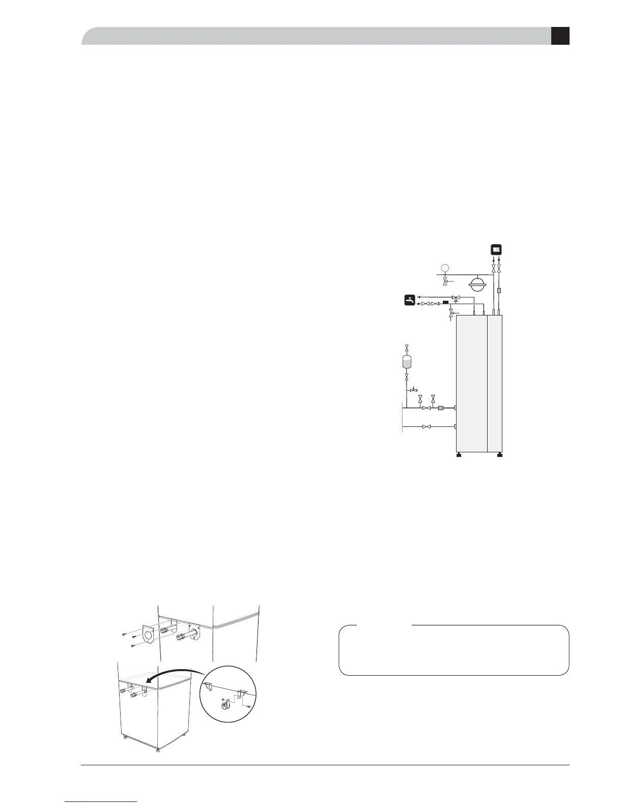
Connecting the heating medium
Pipe connections for the heat medium side are made at
the top.
All required safety devices, shut-off valves (as close to
the heat pump as possible), and particle fi lter (supplied)
must be fi tted.
The safety valve must have a maximum 2.5 bar open-
ing pressure and be installed on the outgoing heat-
ing medium as illustrated. The overfl ow pipe from the
safety valve must be routed enclosed along its entire
length to prevent water pockets and be frost proof.
When connecting to a system with thermostats on all
radiators, a relief valve must be fi tted, or some of the
thermostats must be removed to ensure suffi cient fl ow.
Connecting the hot water heater
The hot water heater in the heat pump must be supplied
with necessary set of valves.
There must be a mixer valve if the temperature exceeds
60 °C.
The safety valve must have a maximum 9.0 bar open-
ing pressure and be installed on the incoming domestic
water line as illustrated. The overfl ow pipe from the
safety valve must be routed enclosed along its entire
length to prevent water pockets and be frost proof.