NIBE FIGHTER 1250
B
General
Pipe installation must be carried out in accordance with
current norms and directives. The heat pump can operate
with a return temperature of up to 56 °C and an outgoing
temperature from the heat pump of 65 °C.
FIGHTER 1250 is not equipped with shut off valves; these
must be installed outside the heat pump to facilitate any
future servicing.
During assembly of FLM the pipes for the heating medium
and hot water heater and possibly hot water circulation are
routed backwards. The distance between FIGHTER 1250
and the wall ought to be 50 mm.
A BI II III I II
50 .0 C
Var mv a tt e nt e m pe r at u r
13.43
1.0
P
A
525
180
400
600
455
145
140
50
45
100
245
640
1750
65
63025-50
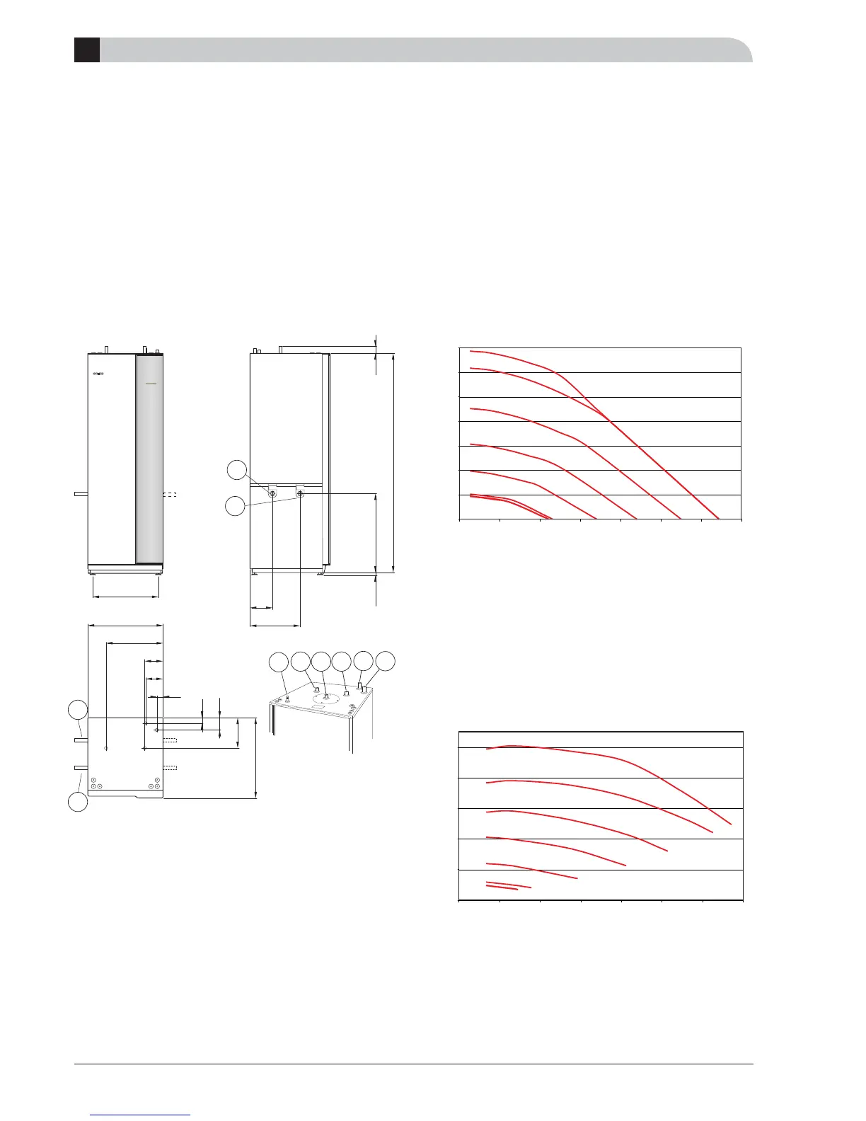
Dimensions and pipe connections
Pipe connections
Pipe connections
Collector
The length of the collector hose varies depending on the
rock/soil conditions and on the heating system, e.g. radia-
tors or under fl oor heating.
Max length per coil for the collector should not exceed
400 m.
Where there is more than one collector, they must be con-
nected in parallel, with a means of adjusting the fl ow.
For surface soil heat, the hose should be buried at a depth
of about 1 metre and the distance between the hoses
should be at least 1 metre.
For several bore holes, the distance between the holes
must be at least 15 metres.
Alternative: Pipe connection (4, 5) can also be made to the right.
Pumps
Circulation pump
Set the HM fl ow by setting the Circ. pump’s control sig-
nal in the relevant menu. The signal changes the pump’s
speed.
The fl ow for hot water heating menu 1.11.4 and 1.11.5 is
set to an optimal value at the factory.
The fl ow for house warming is set to max, and changed
when necessary in menu 2.7.
The fl ow for pool heating is set at 50 %, and changed in
menu 8.4.5.
Brine pump
Control of the brine fl ow occurs automatically. The temper-
ature difference between KBin and KBut is normally main-
tained within 2 - 5 ºC.
0
0,1
0,2 0,3 0,4 0,5 0,6 0,7
Flöde l/s
Tryckfallsdiagram VB-pump
100
90
70
50
30
10
2
Styrsignal
0,01
0,02
0,03
0,04
0,05
0,06
0,07
Difftryck
MPa
0
0
0,1
0,2 0,3 0,4 0,5 0,6 0,7
Flöde l/s
Tryckfallsdiagram KB-pump
0,02
0,04
0,08
0,06
0,1
Difftryck
MPa
0
100
90
70
50
30
10
2
Styrsignal
5
4
4
5
LEK
70
74
75
73
71
72*
* Only enamel and stain-
less steel.
Pressure drop diagram circ.
pump
Operational pressure
Flow l/s
Control signal
Pressure drop diagram brine
pump
Operational pressure
Flow l/s
Control signal