NIBE FIGHTER 1250
Extra shunt ESV 21
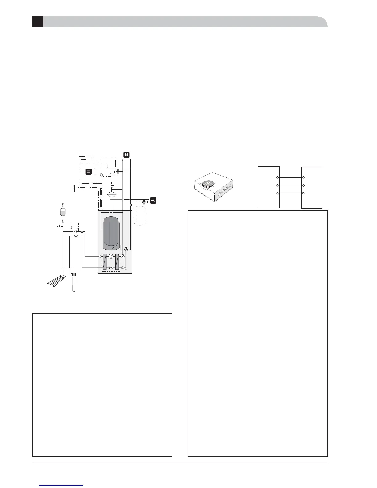
This accessory is used when FIGHTER 1250 is installed in
houses with two different heating systems that require dif-
ferent fl ow line temperatures, for example, in cases where
the house has both a radiator system and an under fl oor
heating system. Heating system 1 covers the system that
requires the greater temperature and that is connected to
the normal fl ow line respectively return line connection.
Heating system 2 covers the heating system that works at
the lower temperature.
Quick guide– menu settings Extra shunt
ESV 21
Menu 8.1.1 Menu type [N]
The menu type is chosen here.
[N] Normal, covers the normal user's needs.
[E] Extended, shows all menus except the service menus.
[S] Service, shows all menus, returns to the previous
menu level 30 minutes after the last button was
pressed.
Selection option Normal, Extended or Service.
- Factory setting: Normal
Select “Service”.
Menu 9.2.5 System 2 present [S]
Select ”On” if heating system 2 is installed. Menu 3.0
can be accessed.
Selection option Off and On.
- Factory setting: Off
D
Accessories
Room sensor RG 10
The room sensor is primarily intended to correct decreases in
room temperature due to causes other than changes in the
outdoor temperature, for example, solar incident radiation.
The required temperature can be set using the knob on the
room sensor unit. The number 5 corresponds to 21 °C (de-
pending on house type relevant setting of the heat curve
and parallel offset). The set temperature can be read on
the display screen on the heat pump.
The room sensor corrects the parallel offset so that the
fl ow temperature changes. If the room temperature chang-
es, the room sensor senses it and allows the control com-
puter to change the fl ow line temperature.
Any radiator valves ought to be fully open in areas that the
room sensor is to control.
For connection, see section B (Electrical connections
”External contacts”).
Quick guide – menu settings Room sensor
RG 10
Menu 8.1.1 Menu type [N]
The menu type is chosen here.
N] Normal, covers the normal user's needs.
[E] Extended, shows all menus except the service menus.
[S] Service, shows all menus, returns to the previous
menu level 30 minutes after the last button was
pressed.
Selection option Normal, Extended or Service.
- Factory setting: Normal
Select “Service”.
Menu 9.2.18 Room sensor type [S]
Room sensor type is selected here. Menu 6.0 can be ac-
cessed.
Selection option From, RG05, RG10 or Room unit
- Factory setting: Off
Menu 6.1 Room compensation [E]
A factor is selected here that determines how much the
fl ow temperature is affected by the difference between
the room temperature and the set room temperature. A
higher value gives a greater change.
The value can be set between 0.2 and 3.0.
- Factory setting: 1,0
Menu 6.2 Heating system [E]
You select here whether the room sensor should acti-
vate heating system 1 (menu 2.0) or heating system 2
(menu 3.0).
Selection option From, System 1, System 2 or System 1+2.
- Factory setting: Off
LEK