EN
10 – English
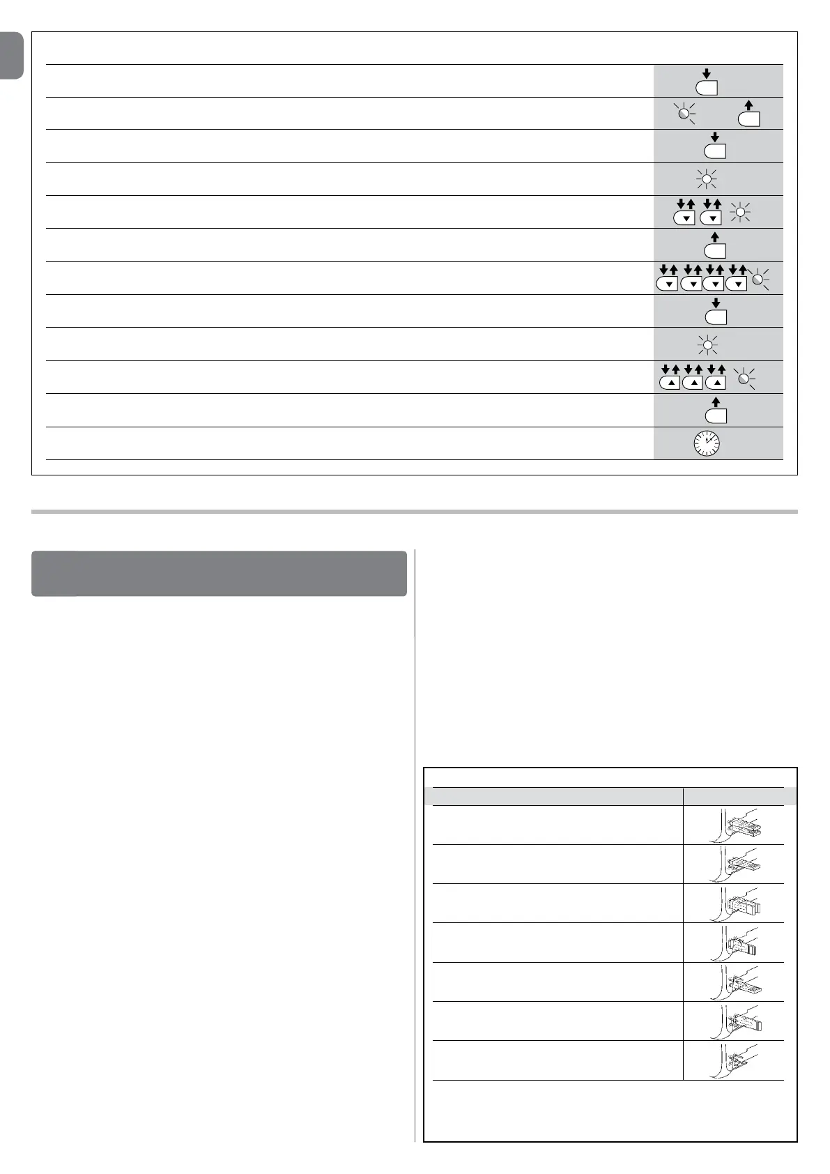
Leveltwo: The sequence to follow in order to change the factory settings of the parameters increasing the “PauseTime” to 60 seconds (input on L1
and level on L5) and reducing the “MotorForce” for light gates (input on L5 and level on L2) have been included as examples:
01. Press and hold the “Set” key for about 3 seconds;
02. Release the key when the L1 LED starts ashing;
03. Press and hold the “Set” key; the “Set” key must be kept pressed during steps 5 and 6;
04. Wait approx. 3 seconds until LED L3, representing the current level of the “Pause Time”, lights up;
05. Press the t key twice to move the LED which is lit to LED L5 which represents the new “Pause Time” value;
06. Release the “Set
” key;
07. Press the t key 4 times to ove the ashing LED to LED L5;
08. Press and hold the “Set” key; the “Set” key must be kept pressed during steps 9 and 10;
09. Wait approx. 3 seconds until LED L5, representing the current level of the “Motor Force”, lights up;
10. Press the s key 3 times to move the LED which is lit to L2 which represents the new “Motor Force” value;
11. Release the “Set
” key;
12. Wait 10s to exit the programming mode automatically after the maximum time interval.
L5
L2
10 s
SET
3 s
L5
SET
SET
L1
L5
SET
3 s
SET
L3 3 s
SET
FURTHERDETAILS
9
9.1- Addingorremovingdevices
Devices can be added to or removed from the SLIGHT automation system at
any time. In particular, various device types can be connected to “BlueBUS”
and “STOP” input as explained in the following paragraphs.
Afteryouhaveaddedorremovedanydevices,theautomationsystem
mustgothroughtherecognitionprocessagainaccordingtothedirec-
tionscontainedinparagraph“9.1.6Recognitionofotherdevices”.
9.1.1-BlueBUS
BlueBUS technology allows you to connect compatible devices using only two
wires which carry both the power supply and the communication signals. All
the devices are connected in parallel on the 2 wires of the BlueBUS itself. It is
not necessary to observe any polarity; each device is individually recognized
because a univocal address is assigned to it during the installation. Photocells,
safety devices, control keys, signalling lights etc. can be connected to Blue-
BUS. The SLIGHT control unit recognizes all the connected devices individually
through a suitable recognition process, and can detect all the possible abnor-
malities with absolute precision. For this reason, each time a device connected
to BlueBUS is added or removed the control unit must go through the recogni-
tion process; see paragraph “9.1.6 Recognition of Other Devices”.
9.1.2-STOPinput
STOP is the input that stops movement immediately, followed by a brief reverse
of the manoeuvre. Devices with contact types Normally Open (NO), Normally
Closed (NC) or devices with a constant resistance of 8.2KΩ, such as safety
edges can be connected to this input.
During the recognition stage the control unit, like BlueBUS, recognizes the type
of device connected to the STOP input (see paragraph “9.1.6 Recognition
of Other Devices”); subsequently it commands a STOP whenever a change
occurs in the recognized status.
Multiple devices, even of different type, can be connected to the STOP input if
suitable arrangements are made.
• Any number of NO devices can be connected to each other in parallel.
• Any number of NC devices can be connected to each other in series.
• Two devices with constant 8.2KΩ constant resistance output can be con-
nected in parallel; if needed, multiple devices must be connected “in cas-
cade” with a single 8.2KΩterminal resistance.
• It is possible to combine Normally Open and Normally Closed by making 2
contacts in parallel with the warning to place an 8.2KΩ resistance in series
with the Normally Closed contact (this also makes it possible to combine 3
devices: Normally Open, Normally Closed and 8.2KΩ).
IMPORTANT–IftheSTOPinputisusedtoconnectdeviceswithsafe-
tyfunctions,onlythedeviceswith8.2KΩconstantresistanceoutput
guaranteethefail-safecategory3accordingtoENstandard954-1.
9.1.3-Photocells
By means of addressing using special jumpers, the “BlueBUS” system enables
the user to make the control unit recognise the photocells and assign them with
a correct detection function. The addressing operation must be done both on
TX and RX (setting the jumpers in the same way) making sure there are no other
couples of photocells with the same address.
TABLE9-PHOTOCELLADDRESSES
Photocell Jumpers
FOTO
External photocell h = 50
activated when gate closes
FOTOII
External photocell h = 100 activated when gate
closes
FOTO1
Internal photocell h = 50 activated when gate
closes
FOTO1II
Internal photocell h = 100 activated when gate
closes
FOTO2
External photocell activated when gate opens
FOTO2II
Internal photocell activated when gate opens
FOTO3
Single photocell for the entire automation system
IMPORTANT– In the case of the installation of FOTO 3 and FOTO II
together the position of the photocell elements (TX-RX) must comply
with the provisions contained in the photocell instruction manual.
 Loading...