EN
English – 3
3.2.1-Productdurability
Durability is the average economic life span of the product. The value of the life
span is strongly inuenced by the intensity of the manoeuvres, i.e. the sum of all
factors that contribute to product wear, see Table3.
To estimate the life span of your automated device, proceed as follows:
01. Add the values of the items in Table3 regarding the system conditions;
02. In Graph1 from the value obtained above, trace a vertical line until it inter-
sects the curve; from this point trace a horizontal line until it intersects the
line of the “manoeuvre cycles”. The obtained value is the estimated life
span of your product.
The lifetime values specied in the graph are only obtainable if the maintenance
schedule is strictly observed (see chapter “Maintenance schedule”). The esti-
mation of durability is made on the basis of design calculations and the results
of tests performed on prototypes. As it is only an estimation, it does not repre-
sent any form of guarantee on the effective life span of the product.
Exampleofdurabilitycalculation:automationofagatewithadoor4.5m
longwithaweightof250kg,installednearthesea:
Table 3 shows the “severity index” for this type of installation: 10% (“Door length”),
15% (“Door weight”) and 15% (“Presence of dust, sand or salt”).
These indicators must be added together to obtain the overall severity index, which is
in this case 40%. With the value identied (40%), look at the horizontal axis of Graph
1 (“severity index”), and identify the value corresponding to the number of “manoeu-
vre cycles” our product will be able to perform in its life span, about 105,000 cycles.
TABLE4-Technicalspecicationsofelectriccables
Connection Cabletype Maximumpermittedlength
A: Electricity supply line cable 3 x 1.5 mm
2
30 m (note1)
B:Flahing light with aerial No.1 cable 2x0.5mm
2
20m
No.1 RG58 type of protected cable 20m (recommended less than 5m)
C:Photocells No.1 cable 2x0.5mm
2
30m (note2)
D:Key selector No.2 cables 2x0.5mm
2
(note3) 50m
E:Fixed edges No.1 cable 2x0.5mm
2
(note4) 30m
F:Movable edges No.1 cable 2x0.5mm
2
(note4) 30m (note5)
Note1 – power supply cable longer than 30 m may be used provided it has a larger gauge, e.g. 3x2.5mm
2
, and that a safety earthing system is provided
near the automation unit.
Note2 – If the “BLUEBUS” cable is longer than 30 m, up to 50 m, a 2x1mm
2
cable is needed.
Note3 – A single 4x0.5mm
2
cable can be used instead of two 2x0.5mm
2
cables.
Note4 – if there is more than one edge, please refer to paragraph “9.1.2 STOP input” for the type of recommended connection.
Note5 – special devices which enable connection even when the leaf is moving must be used to connect movable edges to sliding leaves.
WARNING!–Thecablesusedmustbesuitedtothetypeofenvironmentoftheinstallationsite.
0
10 20 30 40 50 60 70 80 90 100
20.000
40.000
60.000
80.000
100.000
120.000
140.000
160.000
180.000
200.000
220.000
240.000
260.000
GRAPH1
Severityindex%
Durabilityincycles
Surroundingtemperaturegreaterthan
40°Corlowerthan0°Corhumidity
greaterthan80%
Presenceofdust,sandandsalinity
Setmotorpowerto“level4”
20%
15%
15%
TABLE3
Severityindex%
<3m
3-4m
4-5m
5-6m
<200kg
200-300kg
300-400kg
0%
5%
10%
20%
0%
15%
30%
Leaflengthm
LeafweightKg
3.3-Worksinpreparationforinstallation
La g.2 provides an example of an automation system, produced using Nice
components:
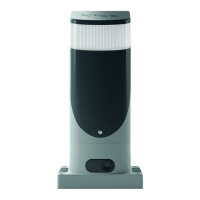
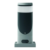
a Key-operated selector switch
b Photocells on post
c Photocells
d Main xed edge (otional)
e Main movable edge
f Rack
g Secondary xed edge (optional)
h Flashing light with incorporated aerial
i Slight
l Secondary movable edge (optional)
These parts are positioned according to a typical standard layout. With refer-
ence to g. 2, locate the approximate position for installation of each com-
ponent envisaged in the system. Important – Before installation, prepare the
electric cables required for the system, with reference to g.2 and to “Table
4-Technicalspecicationsofelectriccables”.
Caution - When laying the ducting for routing the electrical cables, also take
into account that due to possible deposits of water in the routing ducts, the
connection pipelines might create condensate in the control unit, with conse-
quent damage to the electronic circuits.