EN
14 – English
TABELLA17 - Malfunctionsarchive
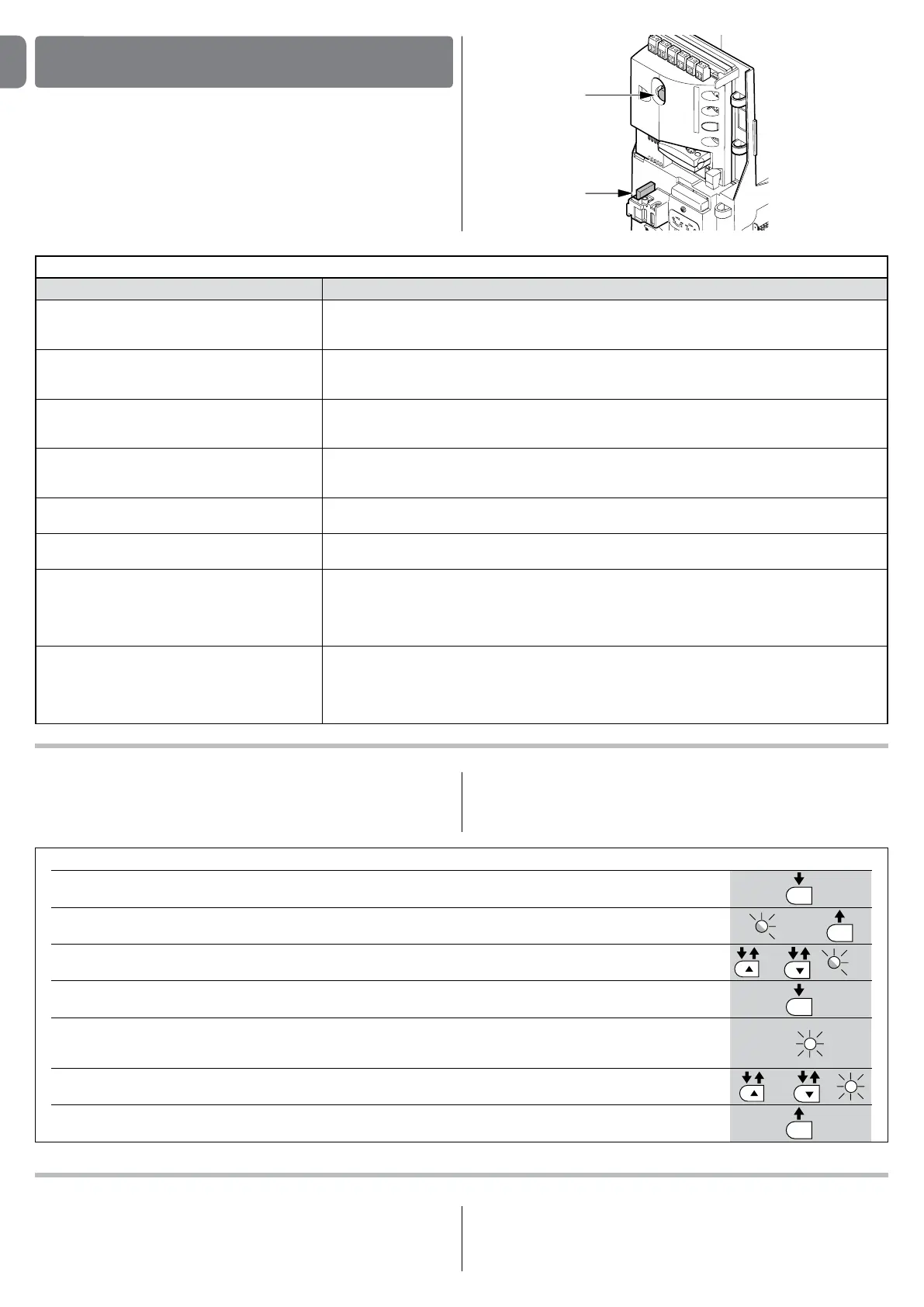
01. Press and hold the “Set” key for about 3 seconds;
02. Release the key when the “L1” LED starts ashing;
03. Press key “
s” or “t” to move the ashing LED onto L8, i.e. the “input LED” for the “malfunctions list” parameter;
04. Press and hold the “Set” key; the “Set” key must be kept pressed during steps 5 and 6;
05. Wait approx. 3s after which the leds corresponding to the manoeuvres subject to faults will light up. The L1 LED
indicates the result of the last manoeuvre and L8 indicates the result of the 8th manoeuvre. If the LED is on, this means
that a defect occurred during that manoeuvre; if the LED is off, this means that no defect occurred during that manoeuvre;
06. Press keys “
s” and “t” to select the required manoeuvre: the corresponding LED ashes the same number of times as
those made by the ashing light after a defect (see table 18);
07. Release the “Set” key.
3 s
SET
SET
SET
SET
L1
or
and
3 s
L8
10.2-Malfunctionsarchive
SLIGHT can display any faults that have occurred in the last 8 manoeuvres, for
example interruption of a manoeuvre due to activation of a photocell or sensi-
tive edge. To check the list of faults, proceed as for Table 17:
10.3-Flashinglightsignalling
During the manoeuvre the ashing light FLASH ashes once every second.
When something is wrong the ashes are more frequent; the light ashes twice
with a second’s pause between ashes.
WHATTODOIF…
(troubleshootingguide)
10
10.1-Troubleshooting
Table 16 contains instructions to help you solve malfunctions or errors that may
occur during the installation stage or in case of failure.
TABLE16-Troubleshooting
Symptoms Recommendedcheck
Theradiotransmitterdoesnotcontrolthe
gateandtheLEDonthetransmitterdoes
notlightup
Check to see if the transmitter batteries are exhausted, if necessary replace them
Theradiotransmitterdoesnotcontrolthe
gatebuttheLEDonthetransmitterlights
up
Check to see if the transmitter has been memorised correctly in the radio receiver
Nomanoeuvrestartsandthe“BlueBUS”
LEDdoesnotash
Check that SLIGHT is powered by a 230V mains supply.
Check to see if the fuses F1 and F2 are blown; if necessary, identify the reason for the failure and then
replace the fuses with others having the same current rating and characteristics.
Nomanoeuvrestartsandtheashinglight
isoff
Make sure that the command is actually received. If the command reaches the STEP-BY-STEP input, the
corresponding “STEP-BY-STEP” LED must light up; if you are using the radio transmitter, the “BlueBus”
LED must make two quick ashes.
Nomanoeuvrestartsandtheashinglight
ashesafewtimes
Count the ashes and check the corresponding value in table 18
Themanoeuvrestartsbutitisimmediately
followedbyareverserun
The selected force could be too low for this type of gate. Check to see whether there are any obstacles;
if necessary increase the force
Themanoeuvreiscarriedoutbuttheash-
inglightdoesnotwork
Make sure that there is voltage on the ashing light’s FLASH terminal during the manoeuvre (being inter-
mittent, the voltage value is not important: approximately 10-30Vdc); if there is voltage, the problem is
due to the lamp; in this case replace the lamp with one having the same characteristics; if there is no
voltage, there may have been an overload on the FLASH output. Check that the cable has not short-
circuited.
ThemanoeuvreiscarriedoutbuttheOpen
GateIndicatordoesnotwork
Check the type of function programmed for the S.C.A. output (Table 7)
When the light should be on, check there is voltage on the S.C.A. terminal (approximately 24Vdc). If
there is voltage, then the problem will have been caused by the light, which will have to be replaced with
one with the same characteristics. If there is no voltage, there may have been an overload on the S.C.A.
output. Check that the cable has not short-circuited.
F1
F2