ID50 Series Panel - Installation, Commissioning & Configuration Manual
Installation Guide - Cabling
20997-263, Issue 4
September 2002
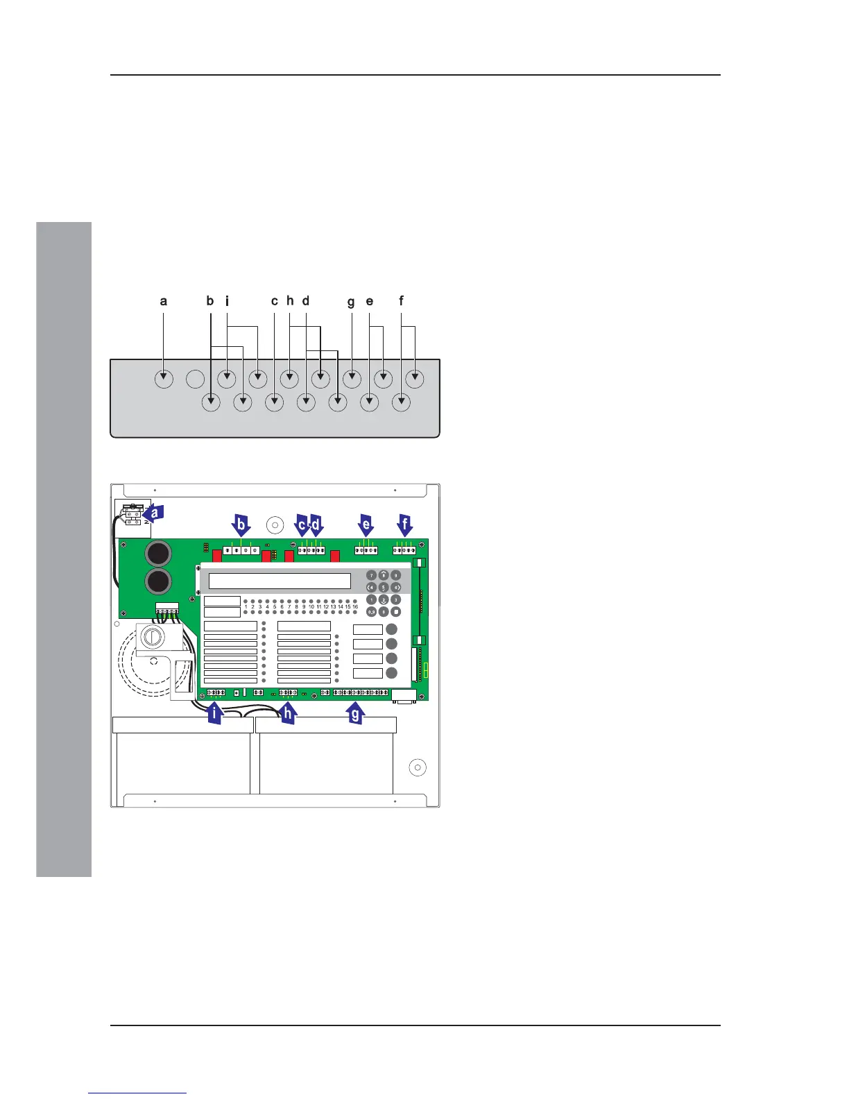
3.1.1 Cable Terminations
This section provides guidance on where to bring cables
into the back box for ease of termination:
a. The mains supply should be brought into the control
panel such that the cable path to the mains termination
block is kept as short as possible.
b. All loop and ancillary cable terminations should be
brought into the panel at suitable positions to ensure
tails are kept as short as possible.
The drawings below show recommended points of entry
so that cabling can meet these requirements.
Knockout/
Termination Point Cable Type
a Power supply cable
b Output D and C cables
c DC Auxiliary Supply
d Sounder Output B and A
e Loop Wiring
f RS485 Communications
g FBF Connections
(Not Supported)
h Digital / ÜE
(ÜE Not Supported)
i -VE Outputs
Note: The FBF Signal and Power supply
cables (g), and Digital / ÜE (h) port 2
are only valid when the panel is in VdS
mode.
For specific PCB cable termination details
see Commissioning:
Section 4.4.1, Loop Wiring,
Section 4.4.2, RS485 Communications Link,
Section 4.4.3, DC Auxiliary Output,
Section 4.4.4, Sounder Circuits Outputs A and B,
Section 4.4.5, CFG Outputs C and D,
Section 4.4.6, -VE Outputs, and
Section 4.4.7, Digital / ÜE Inputs.