3. Installations
The installations described below should be made by qualified service personnel or system
installers.
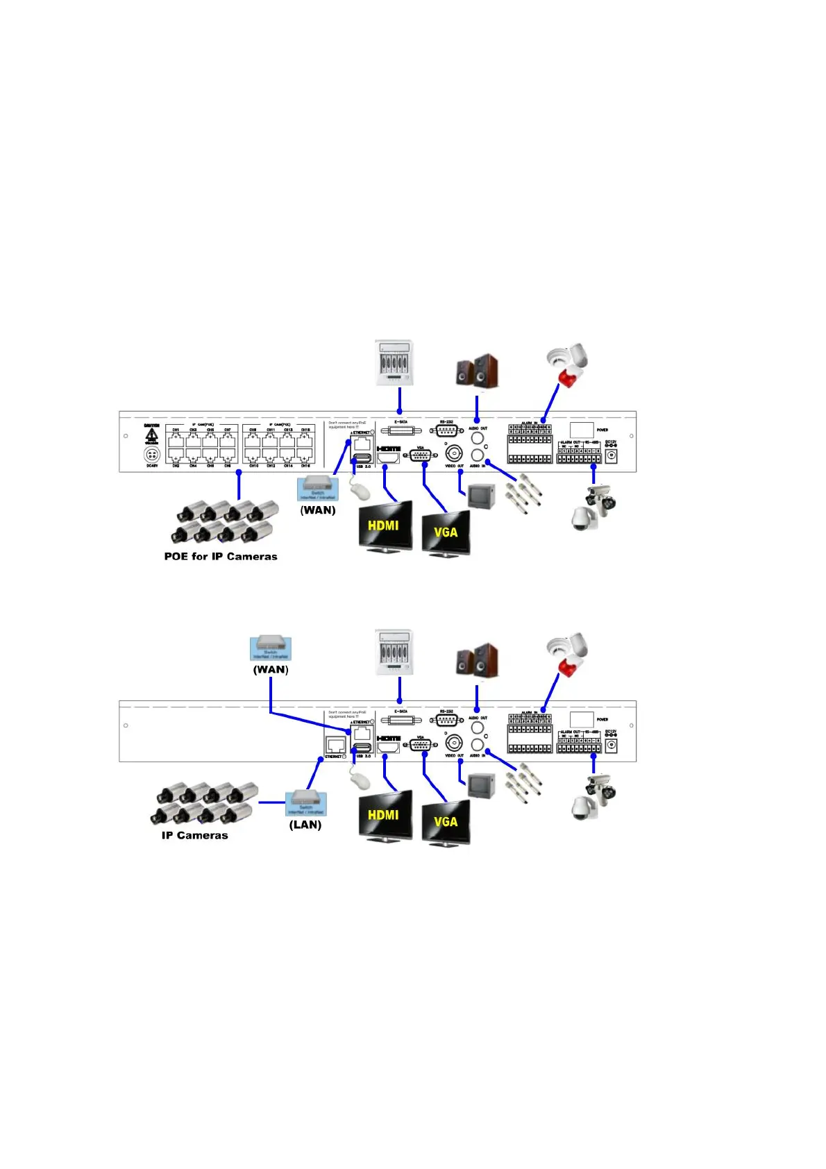
3.1 Basic Connections
Please refer to the following diagram for the connections.
Please make sure to set the NTSC/PAL Selector Switch on the main board according to the
local TV system for the system to work correctly.
Cameras
PoE model: Connects the network camera to each Ethernet connector via the network
cable to POE.
Non-PoE models: Connects the network camera to the Ethernet connector of the LAN
via the network cable.
Main monitor
Connect the main monitor output connector (BNC/VGA/HDMI) to a surveillance TV/VGA
monitor. The TV/VGA monitor displays selected live or recorded cameras in any