46
Chapter 3 Installation and Connection
HIGH FLOW INSUFFLATION UNIT UHI-4
• Avoid applying excessive force to the communication cable.
Otherwise, wire disconnection or other failure may result.
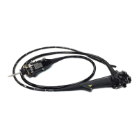
• Communication cable has the LINK-IN plug (26-pin) and the
LINK-OUT plug (14-pin). the LINK-IN plug can be connected
to the LINK-IN connector of the device. the LINK-OUT plug
can be connected to the LINK-OUT connector of the device.
Figure 3.9
• The high flow insufflation unit communicates mutually with
the connected equipment. The communication cable can be
connected to either the LINK-IN or LINK-OUT connector of
the high flow insufflation unit. When the communication cable
is connected to the LINK-OUT connector of the high flow
insufflation unit, for example, the other end of the cable
should be connected to the LINK-IN connector of the other
piece of equipment.
However, always use the LINK-IN connector when
connecting the high flow insufflation unit to the light source or
video system center (refer to Section 3.7, “Connecting the
light source (CLV-190, CLV-S190) or the video system center
(OTV-S190)” on page 52). If another instrument (the
ultrasonic generator or the electrosurgical generator) is
additionally combined, the communication cable should be
connected to the LINK-OUT connector of the high flow
insufflation unit.
LINK-OUT plug
LINK-IN plug
 Loading...