2-4
2. Hardware
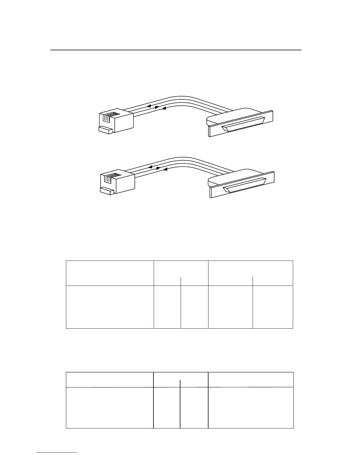
Figures 2-4A and Figure 2-4B show the four-wire RS-232 connections between the
host computer/controller using either a 9-pin or 25-pin “D” connector and the meter
(point-to-point full duplex, with RTS handshake).
Figure 2-4A. RJ-11 to D9 Connector
Figure 2-4B. RJ-11 to D25 Connector
Table 2.1 shows the pin connection assignments between the RS-232 connection on
the meter and the 9-pin or 25-pin “D” connectors of your computer.
Table 2.1. Meter Hookup (RS-232) to the Computer
METER COMPUTER
(DCE) (DTE)
PIN SIGNAL/FUNCTION RJ-11 RJ-12 D9 D25
RTS, meter from computer 1 2 7 4
TX, meter = RX, computer 2 3 2 3
RX, meter = TX, computer 3 4 3 2
Return 4 5 5 7
NC (not connected) 1,6 (all others)
Table 2.2 shows the pin connection assignments between the RS-232 connection on
the meter and the 9-pin or 25-pin “D” connectors of your printer.
Table 2.2. Meter Hookup (RS-232) to the Printer
METER PRINTER
PIN SIGNAL/FUNCTION RJ-11 RJ-12 FUNCTIONS
RTS, meter 1 2 Data Terminal Ready (DTR)
TX, meter 2 3 Received Data (RXD)
RX, meter 3 4 Not Connected
Return 4 5 Signal Return
NC (not connected) 1,6

 Loading...


