2-6
2. Hardware
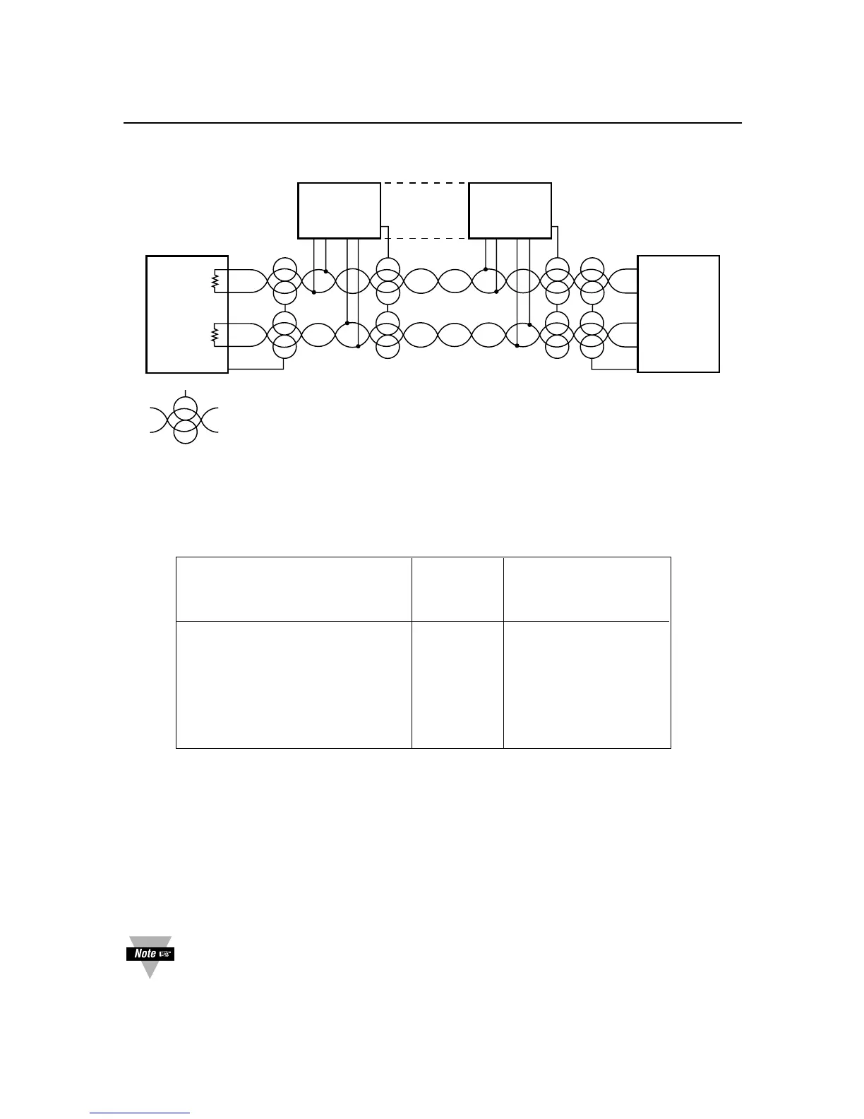
Figure 2-6. Multipoint Full-Duplex RS-485 Connection
Table 2.4. Full-Duplex Hookup to the Computer
METER COMPUTER
(DCE) (DTE)
PIN SIGNAL/FUNCTION RJ-12 D9/D25
+TX 1 (SEE MFG DWG)
–TX 3 (SEE MFG DWG)
+RX 2 (SEE MFG DWG)
–RX 4 (SEE MFG DWG)
RTN 5 (SEE MFG DWG)
NC (not connected) 6
Both HALF DUPLEX (Figure 2-5) and FULL DUPLEX RS-485 (Figure 2-6)
communications require a 6-wire RJ-12 plug to be connected to the RJ-12 jack at the
rear of the meter.
Unlike RS-232, there presently is no established standard D9 or D25 connector pin-
out for RS-485; refer to your computer or controller manual to insure the right cable
connections.
If communications with your meter has failed, it is recommended that you
check for the receive portion of the RS-485 board on DTE (computer). These
lines should be pulled up for +RX and pulled down for –RX with resistors with
a resistance value from 330 ohms to 1K ohms.

 Loading...


