10-29
10. Data Format Commands (P, G, R, W)
10.33 TX/RX TURNAROUND DELAY (SERIAL DELAY SER.dLy)
The four choices provided by the meter for this “20”
command suffix only need two bits of storage, but the
standard byte (two nibbles) is used, so that the MSN = 0.
Turn-around delay is normally used on half-duplex
systems (e.g., RS-485), not on full duplex (for the
meter, RS-232 or RS-422), but the chosen amount is
applied to any of these by the meter. The delay can
be useful in eliminating the effects of ringing,
reflections or line drop.
EXAMPLE: The computer wants meter #15 hex to use a turn-around delay of 100
milliseconds:
“*15W2002<CR>”, and if set for echo with “BUS.FMt”, the meter replies:
“15W20<CR>”. If point-to-point (only one meter), the “15” address is not used. The
chosen delay is now stored in the EEPROM. To put it into use (move to RAM), send a
hard reset, “*15Z04<CR>”.
10.34
READING, INPUT, or OUTPUT SCALE FACTOR(“RdG SC”, “INP SC”, “OUt SC”)
These items are 3 bytes each (6 HEX- ASCII characters) and their corresponding
command suffixes are:
ITEM COMMAND SUFFIX (HEX)
RdG SC 08
IN SC 0B
OUt SC 17
All three scale factors can be calculated by the meter from entry of two data points (via
pushbutton or diskette); only Reading Scale permits direct entry (to facilitate 1.00000
and other straight-forward values). Scale factor and Offset values, however, are stored
separately inside the meter. If your scale/offset information is in the form of two data
points (O2,I2 and O1,I1, where the O’s are the Outputs for the I’s, Inputs), then
SC = (O2-O1) / (I2-I1)
This value is entered/read with these “08”, “0B” and “17” command suffixes, and also
used in calculating the corresponding Offsets (see Section 10.5 ).
True value for output scale factor is stored in its location in EEPROM. When
the program is running, it combines this value with calibration scale of analog
out board and stores new value in output scale’s RAM location (CALLED
MODIFIED OUTPUT SCALE). Therefore, “P17” for this scale factor should be
used very carefully (avoid using if possible). But with “G17”, the value of
modified output scale factor can be read.
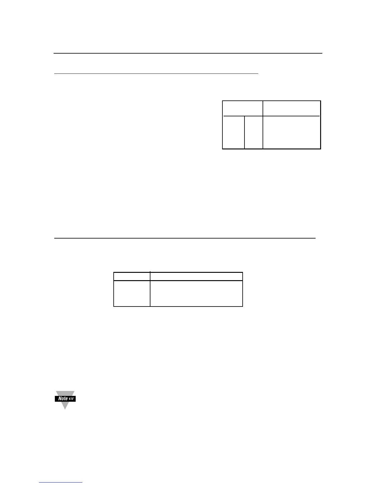
Milliseconds of
BIT # Turnaround delay
000
0130
0 2 100
0 3 300
TABLE 10.27.
SERIAL DELAY (“SER.dLy”)

 Loading...


