2-5
2. Hardware
Logic symbols are opto-isolated, and drive power is obtained from a galvanically-
isolated transformer winding so that the differential signals (minimum ±2 V) will not be
altered by an external ground; earthing of the external transceiver power supply is
recommended to limit common-mode voltage.
The RS-485 hardware may be operated point-to-point (e.g., as RS-422 equipment),
OR
in multipoint, sharing the bus wires with up to 32 other meters.
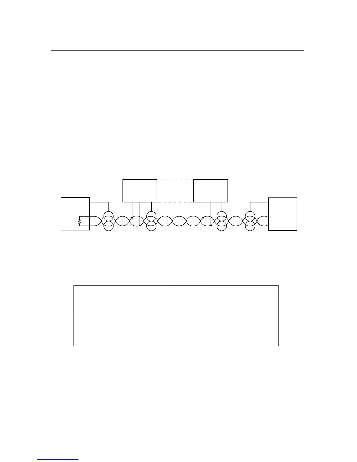
The RS-485 cabling may be a single pair of wires (usually with a shield) for HALF
DUPLEX (Figure 2-5), or two such pairs for FULL DUPLEX (Figure 2-6). The
configurations shown are for bus operation, with tap-offs for each meter.
Figure 2-5. Multipoint, Half-Duplex RS-485 Connection
Table 2.3. Half-Duplex Hookup (RS-485) to the Computer
METER COMPUTER
(DCE) (DTE)
PIN SIGNAL/FUNCTION RJ-12 D9/D25
RX 2 (SEE MFG DWG)
TX 3 (SEE MFG DWG)
RTN 5 (SEE MFG DWG)
RS-422/RS-485 multipoint interconnections between the computer (DTE) and the
meter (DCE) are less well defined because different computer/controller manufacturers
use different pins on their D9 or D25 connectors.

 Loading...


