10-26
10. Data Format Commands (P, G, R, W)
10.28 SET SIGN AND DECIMAL POINT FORMAT
Command suffixes “21”, “22”, “23” and “24” set the value of Setpoints 1, 2, 3 and 4
respectively (the last two often used as Alarm 1 and 2). Each setpoint is described by
three bytes (six HEX-ASCII characters), with the sign and decimal point encoded in the
MSN:
(Here, “FFFFFF” represents the 6 displayed decimal digits, the magnitude of the 20
least-significant bits of these 3 bytes.)
1. Bits 0 to 19 belong to the absolute value (99999 for negative values and 999999 for
positive values)
2. Bits 20, 21, 22 belong to the decimalpoint as in Table 10.26
3. Bit 23 belongs to sign where 0 is positive and 1 is negative as in Table 10.26
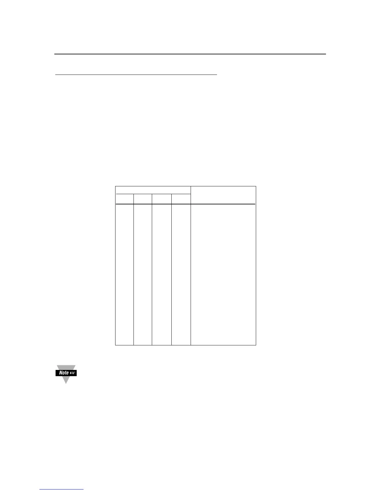
TABLE 10.26 SETPOINT VALUES, BITS 23, 22, 21, AND 20
BIT PATTERN SIGN AND
23 22 21 20 DECIMAL POINT
0000 Not used
0001 +FFFFF.
0010 +FFFFF.F
0011 +FFFF.FF
0100 +FFF.FFF
0101 +FF.FFFF
0110 +F.FFFFF
0111 Not used
1000 Not used
1001 –FFFFFF
1010 –FFFFF.F
1011 –FFFF.FF
1100 –FFF.FFF
1101 –FF.FFFF
1110 –F.FFFFF
1111 Not used
The following 5 nibbles (HEX-ASCII characters) give the binary magnitude.
Since Setpoint value decimal point is directly related to the system decimal
point (see Section 10.3), select the same decimal for setpoints as selected
for system decimal point.
EXAMPLE: The computer inquires of meter #15 hex what value for Setpoint #3 is
stored in EEPROM (usually the same value as in RAM):
“*15R23<CR>”, and if set for echo (“BUS.FMt”), the meter replies:
“15R23A12345<CR>”, where the magnitude is “12345” in hex, or “74565” in decimal,
and the MSN “A”, from the Table 10.28, sets the final decimal value of Setpoint #3 as
“–7456.5”.

 Loading...


