8-6
8. Command and Response Structure
8.2.4 - COMMAND SUFFIX
The two HEX characters following the command class letter are used to specify the
data, features or menu items which the command affects. Table 8.2 gives the
command letter, suffix, feature affected, and the number of data characters included in
the command.
“00” is not used (reserved for the all-device bus address).
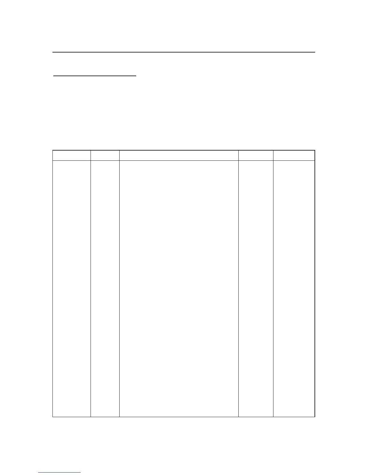
Table 8.2. Command Letters and Suffixes
COMMAND SUFFIX ITEM AFFECTED # CHAR SECTION
D 01 Disable Alarms (SP#3 and SP#4) 0 8.2.3
E 01 Enable Alarms (SP#3 and SP#4) 0 8.2.3
R,W 01 Menu Lockout 2 10.14, 1015
U 01 Setpoints and Alarm Status 0 8.2.3
V 01 Read Data String 0 8.2.3
X 01 Read Unfiltered Value 0 8.2.3
Y 01 Write value to display 6 8.2.3
Z 01 Reset latched alarms 0 8.2.3
D 02 Disable setpoints 1 and 2 0 8.2.3
E 02 Enable setpoints 1 and 2 0 8.2.3
R,W 02 Menu Lockout and Normal Color config 2 10.14,10.15
U 02 Peak/Valley (HI/LO) status 0 8.2.3
X 02 Read Peak (HI) value 0 8.2.3
X Y02 Write value to meter 7 8.2.3
Z 02 Reset averaging filter 0 8.2.3
D 03 Disable display of remote value 0 8.2.3
E 03 Set alarm mode 0 7.2.2
R,W 03 Setpoint (#1,#2) & Alarm Color (#1, #2) 2 10.16
X 03 Read Valley (LO) value 0 8.2.3
Z 03 Soft Reset (RESET1, from RAM) 0 8.2.3
D 04 Hold displayed value 0 8.2.3
E 04 Display “RUN” 0 8.2.3
X 04 Read filtered value 0 8.2.3
Z 04 Hard Reset (RESET2, from EEPROM) 0 8.2.3
D 05 Reset tare, valid only on strain meter 0 8.2.3
E 05 TARE, valid only on strain meter 0 8.2.3
G,P,R,W 05 INPUT, type and range (Rd.SC.OF) 2 10.10
Z 05 Reset Peak/Valley (HI/LO) 0 8.2.3
G,P,R,W 07 RdG.CNF, display controls 2 10.1
G,P,R,W 08 RdG SC, display scale factor 6 10.34
G,P,R,W 09 RdG OF, display offset 6 10.35
G,P,R,W 0A INP.CNF, meter features 2 10.2
G,P,R,W 0B INP SC, input scale factor 6 10.34
G,P,R,W 0C dEC.Pt and CNt by (roundoff) 2 10.3
G,P,R,W 0E FILtER and FILt.tM, filter #s 2 10.4
(continued next page)

 Loading...


