10-8
10. Data Format Commands (P, G, R, W)
10.7 ALARM FUNCTIONS (“AL.CNF and AL.MOdE”)
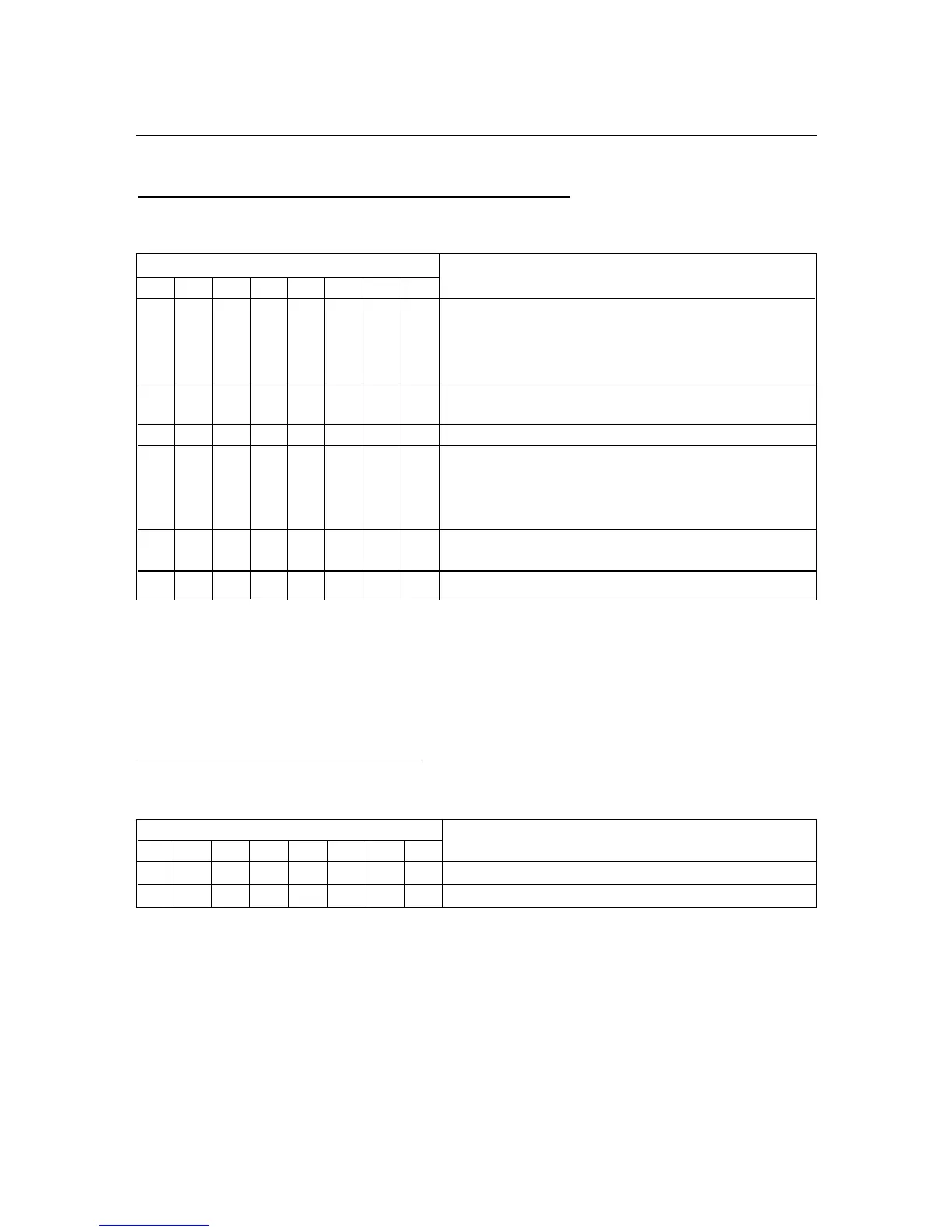
TABLE 10.7 ALARM CONFIGURATION AND MODE
BIT POSITION AL.CNF and AL.MOdE
76543210
00PROC AL1 Process
01HI dEV AL1 HIGH Deviation
10LO dEV AL1 LOW Deviation
11bNd.dEV AL1 BAND Deviation
0 UNLtCH AL1 Un-Latched Alarm
1 LAtCH AL1 Latched Alarm
X (Not Used)
00 PROC AL2 Process
01 HI dEV AL2 HIGH Deviation
10 LO dEV AL2 LOW Deviation
11 bNd.dEV AL2 BAND Deviation
0 UNLtCH AL2 Un-Latched Alarm
1 LAtCH AL2 Latched Alarm
X (Not Used)
EXAMPLE: Set Alarm 1 function mode as Band Deviation, latched and Alarm 2
function mode as Process, latched.
The command data is 01000111 BIN. = 47 HEX. Then send *W1247
10.8 ALARM DELAY: (“NUM.dLy”)
TABLE 10.8 ALARM DELAY
BIT POSITION NUM.dLy (ALARM DELAY)
76543210
XXXX0-15 for AL2
XXXX 0-15 for AL1
EXAMPLE: These 2 bytes enable users to select the number of input readings
required to trigger Alarm 1 (SP3), and Alarm 2 (SP4) action that will delay the alarm
activation. Choose 7 for Alarm 2 and 9 for Alarm 1 as the number of input readings
before meter activates the alarm:
The command data is 10010111 BIN. = 97 HEX. Then send *W1397

 Loading...


