10-20
10. Data Format Commands (P, G, R, W)
10.18 BLOCK B continued
R/W41 (BLOCK B)
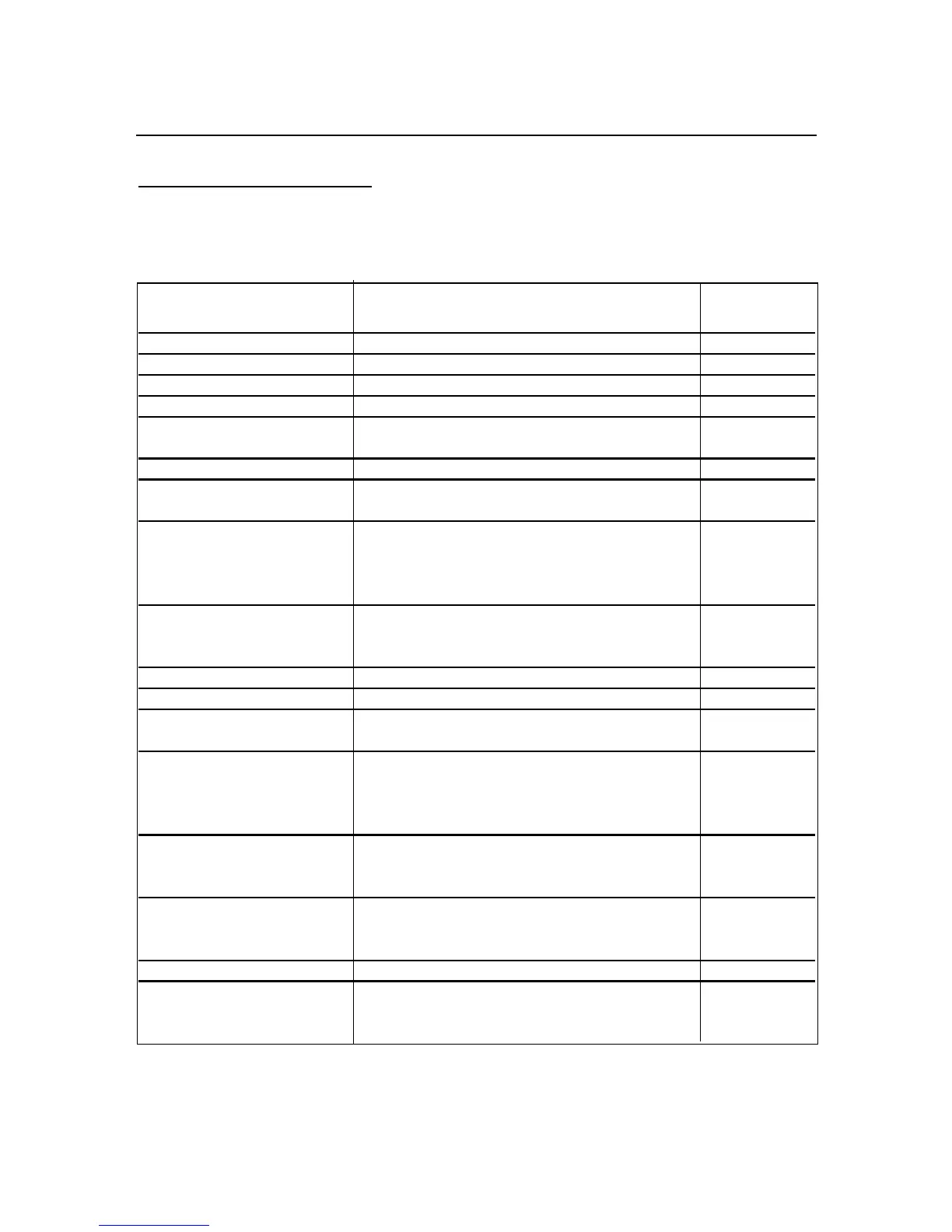
EXAMPLE: To configure meter working with following order and desired options:
FUNCTIONS DESIRED OPTIONS EQUIVALENT
HEX. VALUE
Recognition Character ! 21
Units of Measure mV 6D5600
Serial Delay 100msec. 02
RS-485 Device address 15 0F
COM.PAR & MOdbUS Comm. Parameter: (19.2k, none, 1)
Modbus enabled 0E
NUM.dLy (Alarm Delay) 7 for Alarm 2, 9 for Alarm1 97
AL.CNF & AL.MOdE AL1: Band Dev., latched;
AL2: Process, latched 47
AL.CNF AL1 & AL2 enabled, AL1:above,
normal open, filtered; AL2: below,
normal closed, unfiltered 9C
AL. Reset disabled at P2-11 rear connector.
SP.CNF SP1 & SP2 enabled and flashing;
SP1: above, normal close; 2E
SP2: below, normal open,
INPUt & Rd.SC.OF 0-100 Volt, and enable Rd.SC.OF A3
CNt by & dEC.Pt FFF.FFF 41
OUt.CNF & Ad.RAtE Enabled Analog Output,
0-20mA and A2D conversion rate = 2 43
RdG.CNF Rd.SC.OF direct format,
Decimal Point active,
Display Flashing at Alarm or Setpoint state 14
and LED’s display at high brightness level.
bUS.FMt Checksum excluded, No line feed,
Echo mode on, P-to-P Command mode, 54
RS-485 protocol
DAt.FMt Data String will include:
Alarm / Peak / Valley / current filtered CF
input value status and separated by line.
FILtER 32 75
INP.CNF Line Frequency - 60HZ,
FAST (12/SEC) Reading Rate, 1A
UNIPOLAR, IN.SC.OF- ENABLE
*The command data is in order as follows:
6D5600020F0E97479C2EA341431454CF
Then send: *W416D5600020F0E97479C2EA341431454CF

 Loading...


