M - 6
Note: the Universal Input Meters support only Read Single Register, so the
number of registers should always set to 1.
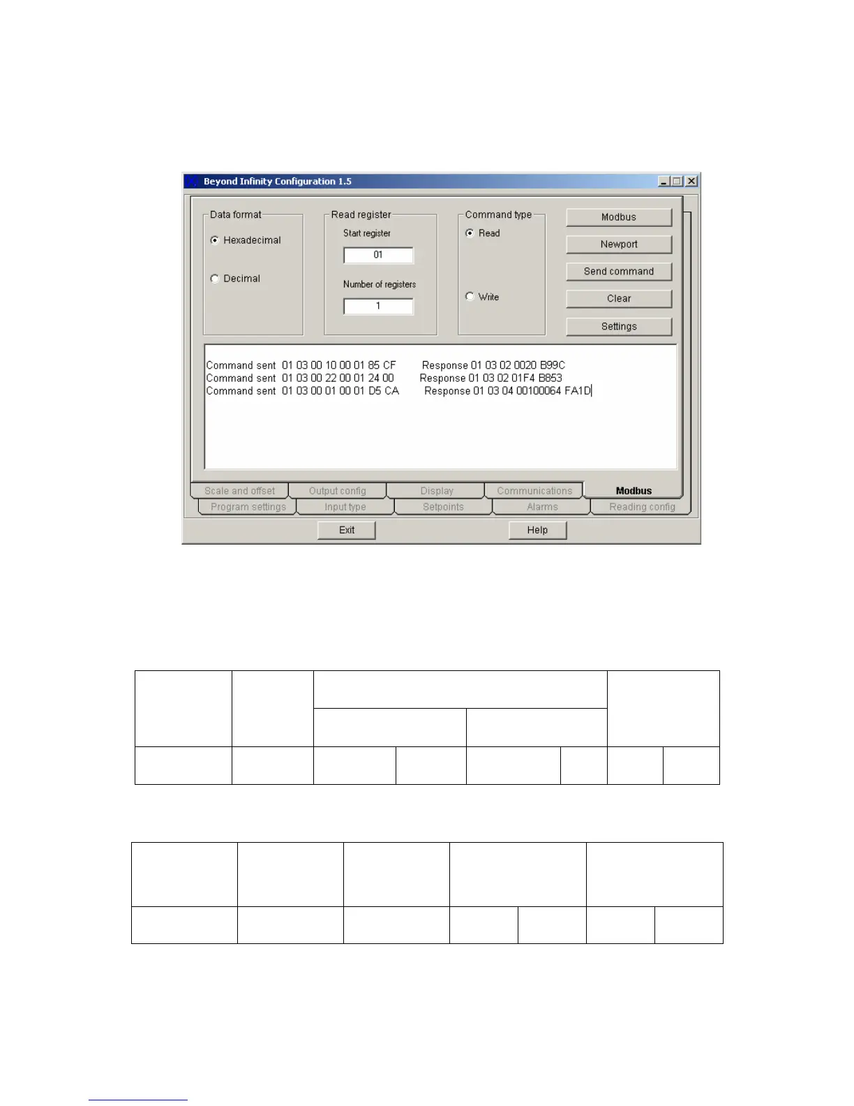
Screenshot for following examples 1- 3:
Figure 8.1: Read Command Samples via Infinity Configuration Software.
Example 1: For one byte data registers: 1
st
data string of Command sent section as
shown on the Figure 8.1:
01 03 0010 0001 85CF : is to read INPUT CONFIGURATION ( INF.CNF and INPUt ).
DATA
DEVICE
ADDRESS
FUNCTION
CODE
03 or 04
STARTING REGISTER NUMBER OF REGISTERS
CRC
01 03 00 10 00 01 85 CF
01 03 02 0000 B844 : 1
st
Command Response on Figure 8.1 which device
responded to the 1
st
read command.
DEVICE
ADDRESS
FUNCTION
CODE
NUMBER OF
BYTES
VALUES OF
REGISTERS
(1 Byte)
CRC
01 03 02
00
(N/A)
20
B9 9C
For detail description of the VALUES OF THE REGISTER above, refer to Table 10.2 of
Communication Manual.

 Loading...


