3. Instructions
644
CS/CJ/NSJ Series Instructions Reference Manual (W474)
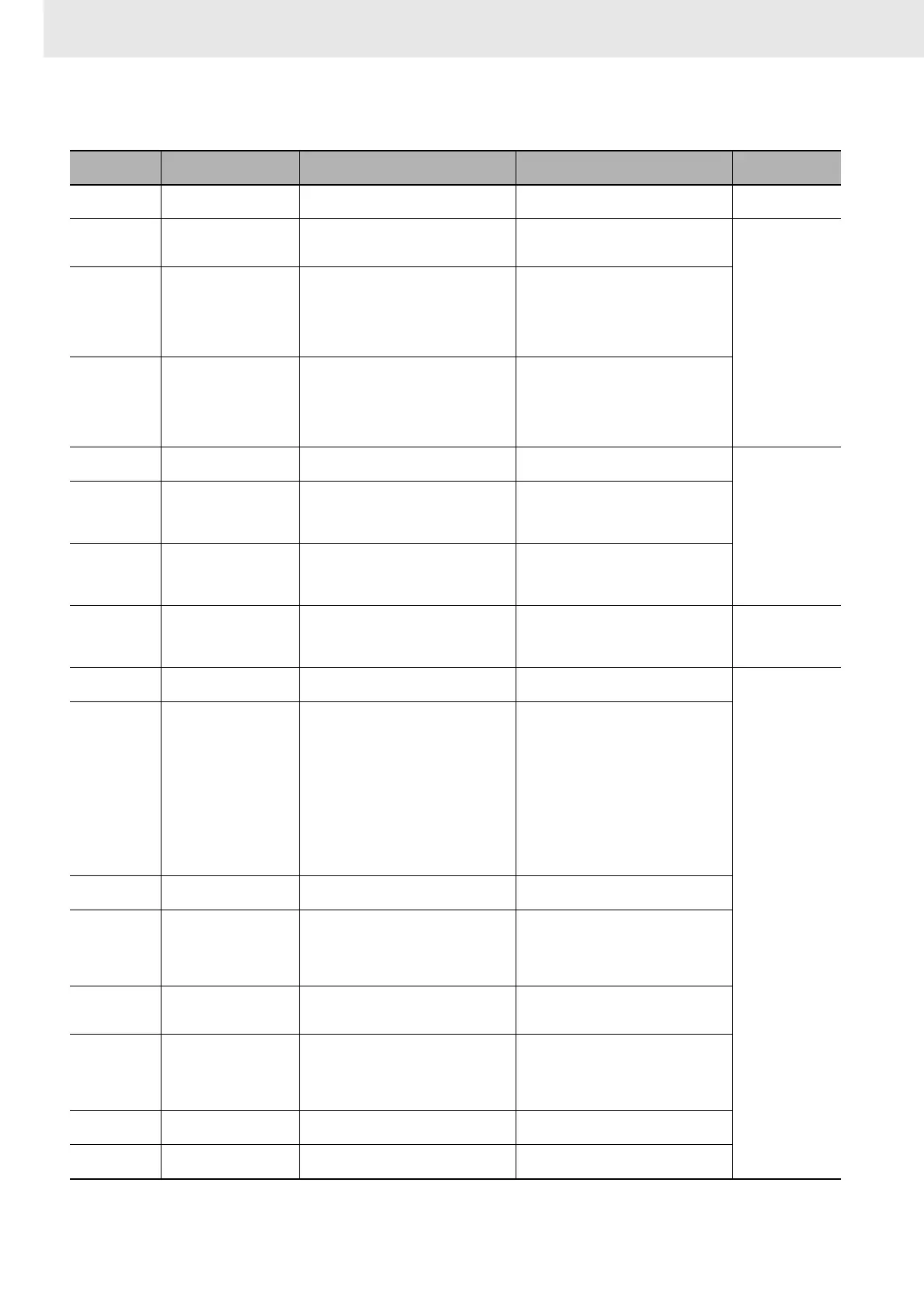
PID Parameter Settings
Control data Item Contents Setting range
Change with ON
input condition
C Set value (SV) The target value of the process being
controlled.
Binary data (of the same number of bits as
specified for the input range)
Allowed
C+1 Proportional band The parameter for P action expressing the
proportional control range/total control
range.
0001 to 270F hex (1 to 9999);
(0.1% to 999.9%, in units of 0.1%)
Can be changed
with input condition
ON if bit 1 of C+5
is 1.
C+2 Tik
Integral Constant
A constant expressing the strength of the
integral action. As this value increases, the
integral strength decreases.
0001 to 1FFF hex (1 to 8191);
(9999 = Integral operation not executed)
When “1” is specified for the
integral/differential constant: 1 to 8191
When “9” is specified: 0.1 to 819.1 s
(See note 1.)
C+3 Tdk
Derivative Constant
A constant expressing the strength of the
derivative action. As this value increases,
the derivative strength decreases.
0001 to 1FFF hex (1 to 8191);
(0000 = Derivative operation not executed)
When “1” is specified for the
integral/differential constant: 1 to 8191
When “9” is specified: 0.1 to 819.1 s
(See note 1.)
C+4 Sampling period (τ) Sets the period for executing the PID
action.
0001 to 270F hex (1 to 9999);
(0.01 to 99.99 s, in units of 10 ms)
Not allowed
Bits 04 to 15 of
C+5
2-PID parameter (α) The input filter coefficient. Normally use
0.65 (i.e., a setting of 000). The filter
efficiency decreases as the coefficient
approaches 0.
000 hex: α = 0.65
Setting from 100 to 163 hex means that
the value of the rightmost two digits is set
from α= 0.00 to α= 0.99. (See note 2.)
Bit 03 of C+5 Manipulated variable
output designation
Designates the manipulated variable
output when the PV equals the SV.
This setting is enabled when there is no
integral operation.
0: Output 0%
1: Output 50%
Bit 01 of C+5 PID constant change
enable setting
The timing of enabling changes made to
the proportional band (P), integral
constant (Tik), and derivative constant
(Tdk) for use in PID calculations.
0: At start of PID instruction execution
1: At start of PID instruction execution and
each sampling period
Allowed
Bit 00 of C+5 PID forward/reverse
designation
Determines the direction of the
proportional action.
0: Reverse action
1: Forward action
Not allowed
Bits 13 to 14 of
C+6
ID starting integral
manipulated variable
designation (unit version
4.0 or later only)
Determines the initial integral manipulated
variable when PID control is started (i.e.,
when the input turns ON).
Bit 14 = 0 and bit 13=0:
Start from same integral manipulated
value as manipulated variable output
designation (Pre-Ver. 4.0 operation).
Bit 14 = 0 or 1 and bit 13 = 1:
Bumpless operation (i.e., start from an
integral manipulated variable that will not
abruptly change the manipulated variable
output and result in a continuous change).
Bit 14 = 1 and bit 13 = 0:
Start with integral manipulated variable =
0.
Bit 12 of C+6 Manipulated variable
output limit control
Determines whether or not limit control will
apply to the manipulated variable output.
0: Disabled (no limit control)
1: Enabled (limit control)
Bits 08 to 11 of
C+6
Input range The number of input data bits. 0: 8 bits 5: 13 bits
1: 9 bits 6: 14 bits
2: 10 bits 7: 15 bits
3: 11 bits 8: 16 bits
4: 12 bits
Bits 04 to 07 of
C+6
Integral and derivative unit Determines the unit for expressing the
integral and derivative constants.
1: Sampling period multiple
9: Time (unit: 100 ms)
(See note 1.)
Bits 00 to 03 of
C+6
Output range The number of output data bits. 0: 8 bits 5: 13 bits
1: 9 bits 6: 14 bits
2: 10 bits 7: 15 bits
3: 11 bits 8: 16 bits
4: 12 bits
C+7 Manipulated variable
output lower limit
The lower limit for when the manipulated
variable output limit is enabled.
0000 to FFFF (binary)
(See note 3.)
C+8 Manipulated variable
output upper limit
The upper limit for when the manipulated
variable output limit is enabled.
0000 to FFFF (binary)
(See note 3.)