649
3. Instructions
CS/CJ/NSJ Series Instructions Reference Manual (W474)
Data Control Instructions
3
PID
Hint
• The setting in bit 1 of C+5 is supported only by CJ2, CJ1, CS1-H, CJ1-H CPU Units and CS1 CPU
Units with lot numbers of 001201@@@@ or later (manufactured December 1, 2000 or later).
• The number of valid input data bits for the measured value is designated by the input range setting in
C+6, bits 08 to 11, and the number of valid output data bits for the manipulated variable output is
designated by the output range setting in C+6, bits 0 to 3. These ranges are shown in the following
table.
If the range of data handled by an Analog Input Unit or Analog Output Unit cannot be set accurately
by setting the number of valid bits, APR(069) (ARITHMETIC PROCESS) can be used to convert to
the proper ranges before and after PID(190).
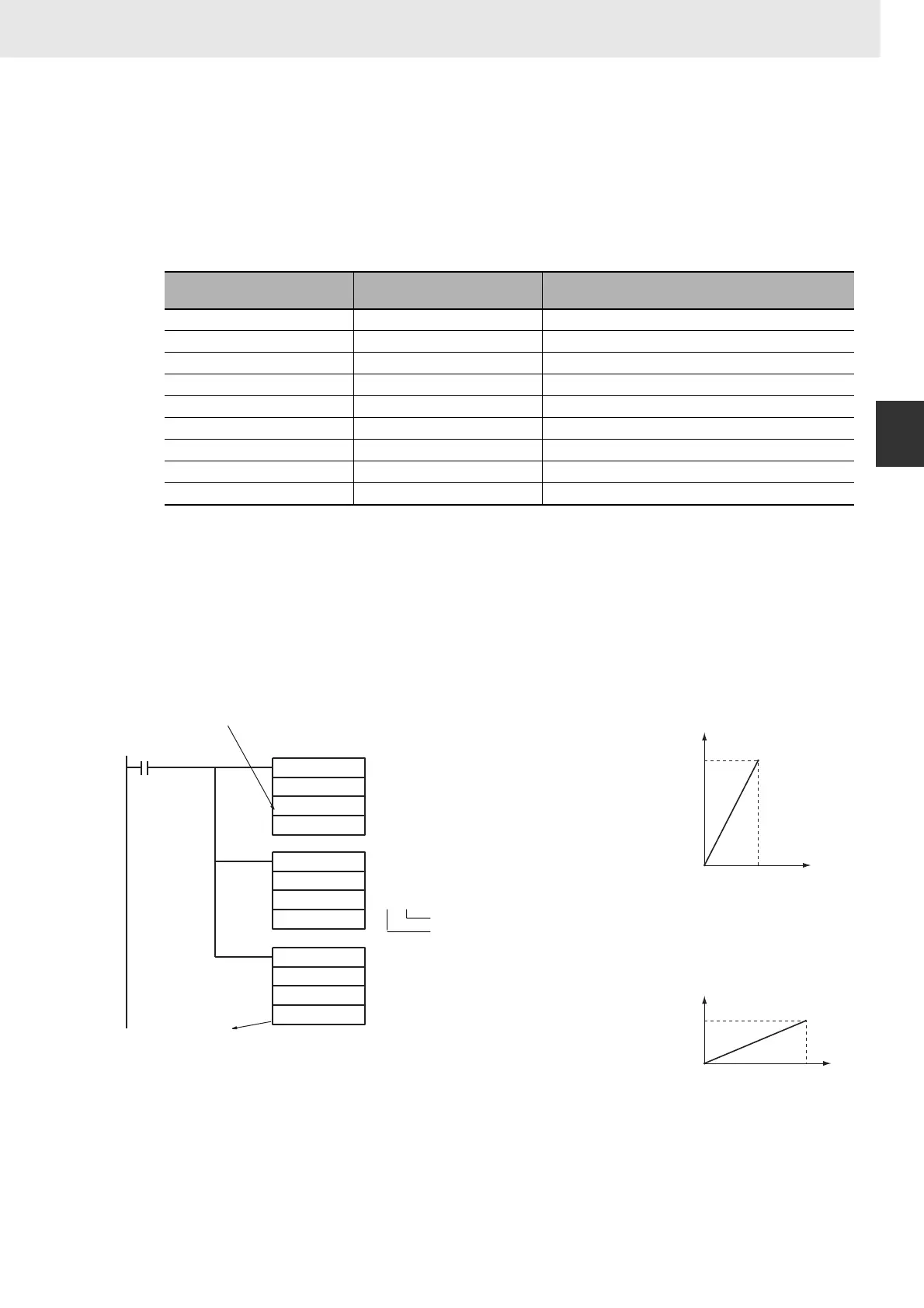
The following program section shows an example for a DRT1-AD04 Analog Input Unit and DRT1-
DA02 Analog Output Unit operating as DeviceNet slaves. The data ranges for these two Units is 0000
to 1770 hex, which cannot be specified merely by setting the valid number of digits. APR(069) is thus
used to convert the 0000 to 1770 hex range of the Analog Input Unit to 0000 to FFFF hex for input to
PID(190) and then the manipulated variable output from PID(190) is converted back to the range
0000 to 1770 hex, again using APR(069), for output from the Analog Output Unit.
C+6, bits 08 to 11 or
C+6, bits 00 to 03
Number of valid bits Range
0 8 0000 to 00FF hex
1 9 0000 to 01FF hex
2 10 0000 to 03FF hex
3 11 0000 to 07FF hex
4 12 0000 to 0FFF hex
5 13 0000 to 1FFF hex
6 14 0000 to 3FFF hex
7 15 0000 to 7FFF hex
8 16 0000 to FFFF hex
APR
PID
APR
D1000
D2000
D2000
D2500
D3000
D3000
D1500
C (D1500):
C+1 (D1501):
C+2 (D1502):
C+3 (D1503):
C+4 (D1504):
C+1 (D1001):
C+2 (D1002):
C+3 (D1003):
C+4 (D1004):
C (D1000):
C+6 (D2506):
@8@8
Control Data
0000 Hex (binary with one table)
1770 Hex (Xm)
0000 Hex (Yo)
1770 Hex (X1)
FFFF Hex (Y1)
Control Data
0000 Hex (binary with one table)
FFFF Hex (Xm)
0000 Hex (Yo)
FFFF Hex (X1)
1770 Hex (Y1)
Control Data
Valid number of bits: 16 (0000 to FFFF Hex)
Valid number of bits: 16 (0000 to FFFF Hex)
From Analog Input Unit
Execution
condition
To Analog Output Unit
Analog input value
Analog output value
X
(hex)
#0000
Y1: #FFFF
Y0: #0000
Y (hex)
X1: #1770
(Xm)
#0000
Y1: #1770
Y0: #0000
Y (hex)
X1: #FFFF
(Xm)
X
(hex)