3. Instructions
886
CS/CJ/NSJ Series Instructions Reference Manual (W474)
• DTXDU(262) will not be executed while the DTXDU(262) Send Ready Flag (n+9/n+19 bit 04) is OFF
(n = CIO 1500 + 25 × unit number). Use the DTXDU(262) Send Ready Flag in an NO input condition
for DTXDU(262).
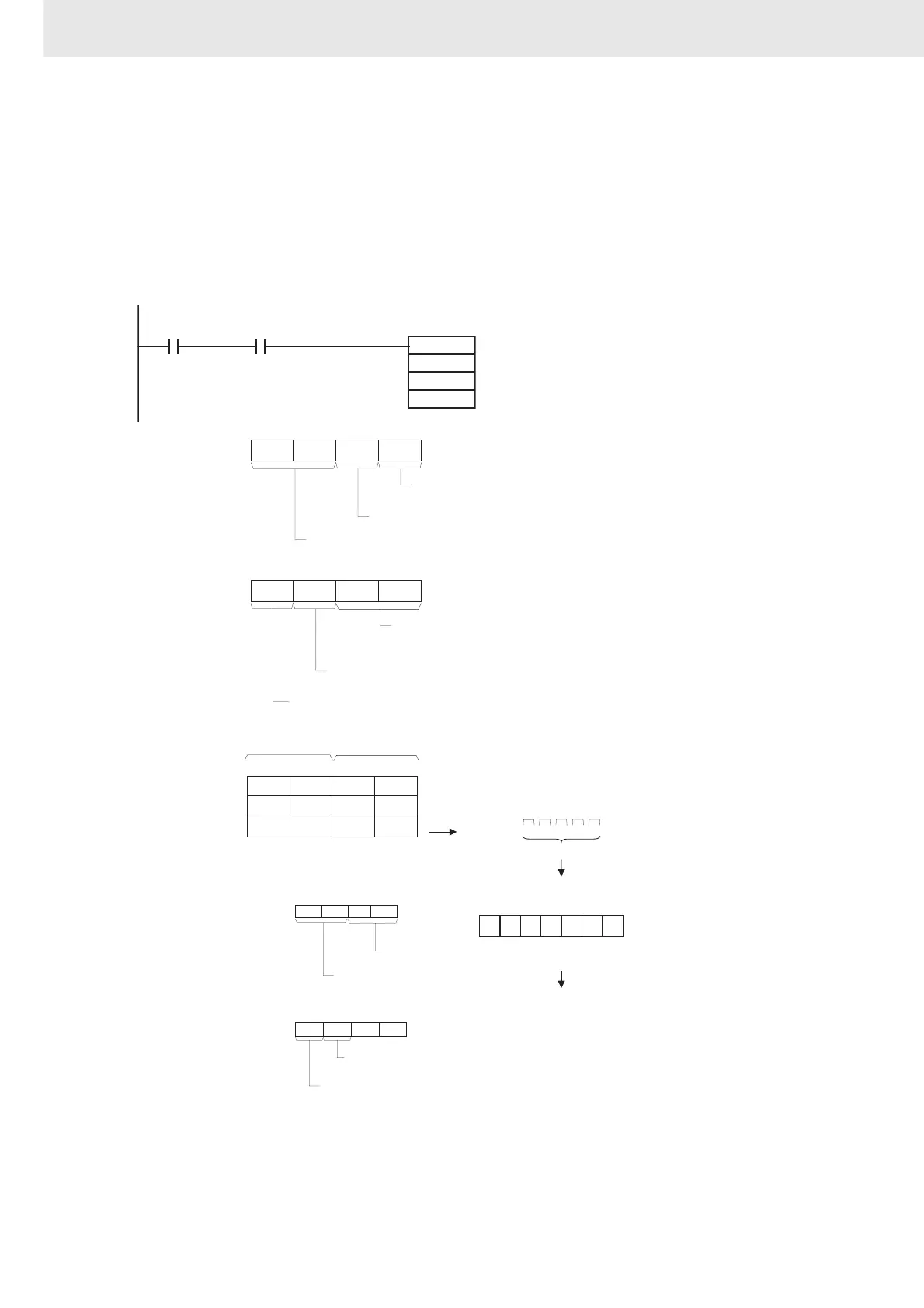
Example Programming
In the following sample, if CIO 0.00 is turned ON while the DTXDU(262) Send Ready Flag (CIO
1559.04) is ON, 5 bytes of data starting from the lower byte of D100 will be sent to the external device
connected to port 1 of the Serial Communications Unit with unit number 2 without converting the data in
any way.
DTXDU
D100
D200
&5
1559.04
0.00
DTXDU(262) Send
Ready Flag
(Unit 2, port 1)
S
C
N
C+0: D200
0
0 7 815
0
11 12
0
0 7 815
1
11 12
0 1
4 3
1 2
4 3
S: D100
0 7 815
4 1 23
D101
D A BC
D102
E F
1 2 3 4 A B C D E F
3412ST AB CD EF ED
D30204
0 7 815
2
11 12
0 3
4 3
0
D30205:
0 7 815
1
11 12
4 3
1
Always 00
RS and ER signal control
0: No RS and ER signal control
Byte order
1: Least significant bytes first
C+1: D201
Serial Communications Unit's unit address (Unit
address as CPU Bus Unit)
12 hex = Unit number + 10 hex
Serial port number
1: Port 1
Data sent.
In this example, a start and end code have been
specified in the allocated DM Setup Area.
ST: Start code (e.g., 02 hex)
ED: End code (e.g., 03 hex)
Most signifi-
cant bytes
Least signif-
icant bytes
Transfer order
5 bytes
Example allocated DM Setup Area settings:
Start code
(02 hex)
End code
(03 hex)
Start code and end code values
Start code and end code specifiers
End code specifier
(1: Use end code.)
Start code specifier
(1: Use start code.)
Always 0