89
Sequence Input Instructions Section 3-2
The following table shows example DM Area ranges in the CP1L L CPU Units.
3-2 Sequence Input Instructions
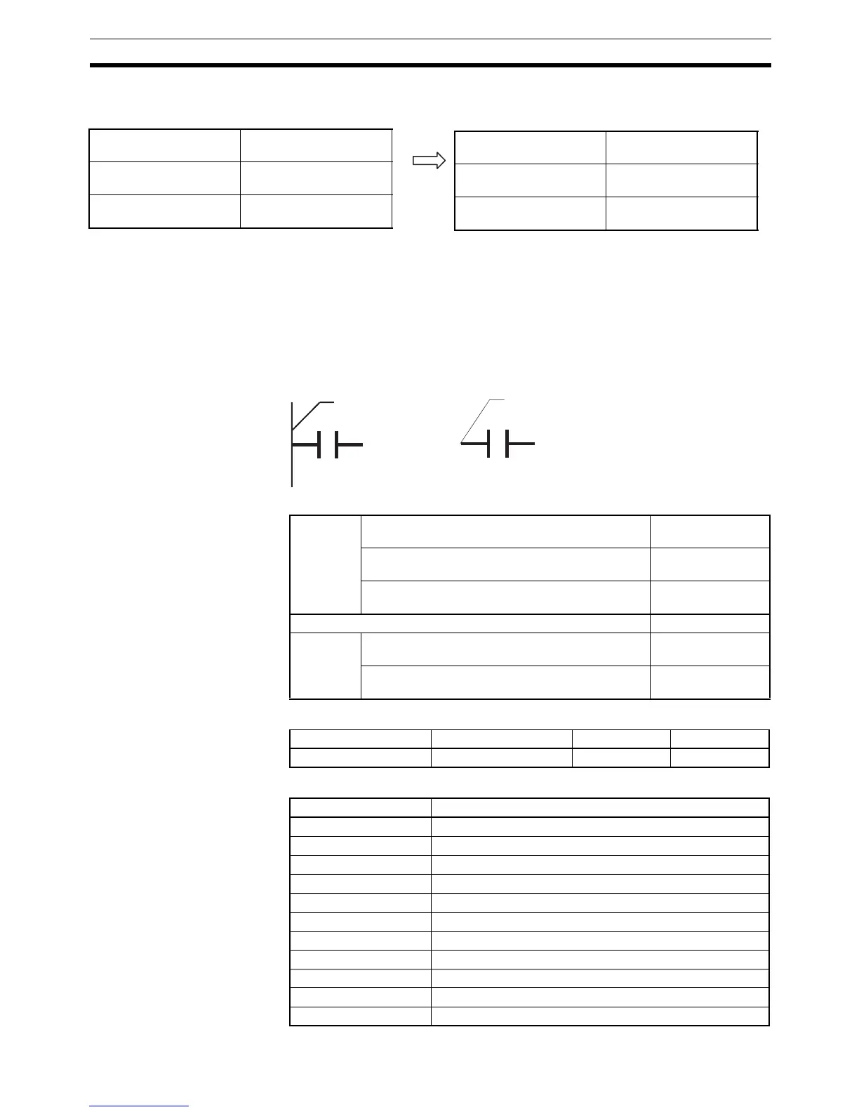
3-2-1 LOAD: LD
Purpose Indicates a logical start and creates an ON/OFF execution condition based on
the ON/OFF status of the specified operand bit.
Ladder Symbol
Variations
Applicable Program Areas
Operand Specifications
CP1H and CP1L M CPU Units
DM Area D00000 to D32767
Indirect DM addresses in
binary
@D00000 to @D32767
Indirect DM addresses in
BCD
*D00000 to *D32767
CP1L L CPU Units
DM Area D00000 to D09999,
D32000 to D32767
Indirect DM addresses in
binary
@D00000 to @D09999,
@D30000 to @D32767
Indirect DM addresses in
BCD
*D00000 to *D09999,
*D30000 to *D32767
Bus bar
Starting point of bloc
Variations Restarts Logic and Creates ON Each Cycle
Operand Bit is ON
LD
Restarts Logic and Creates ON Once for
Upward Differentiation
@LD
Restarts Logic and Creates ON Once for
Downward Differentiation
%LD
Immediate Refreshing Specification !LD
Combined
Variations
Refreshes Input Bit, Restarts Logic, and
Creates ON Once for Upward Differentiation
!@LD
Refreshes Input Bit, Restarts Logic, and
Creates ON Once for Downward Differentiation
!%LD
Block program areas Step program areas Subroutines Interrupt tasks
OK OK OK OK
Area LD operand bit
CIO Area CIO 0.00 to CIO 6143.15
Work Area W0.00 to W511.15
Holding Bit Area H0.00 to H511.15
Auxiliary Bit Area A0.00 to A959.15
Timer Area T0000 to T4095
Counter Area C0000 to C4095
Task Flag Area TK00 to TK31
Condition Flags ER, CY, N, OF, UF, >, =, <, >=, <>, <=, A1, A0
Clock Pulses 0.0 2s, 0.1 s, 0.2 s, 1 s, 1 min
TR Area TR0 to TR15
DM Area ---