716
High-speed Counter/Pulse Output Instructions Section 3-20
C2: Pulses per Revolution
Specifies the number of pulses per revolution (0001 to FFFF hex).
D: First Destination Word
The PV is output to D or to D and D+1.
Operand Specifications
Description PRV2(883) converts the pulse frequency input from high-speed counter 0,
according to the conversion method specified in C1 and the pulses/revolution
coefficient specified in C2, and outputs the result to D and D+1.
Select one of the following conversion methods by setting C1 to 0000 hex or
0001 hex.
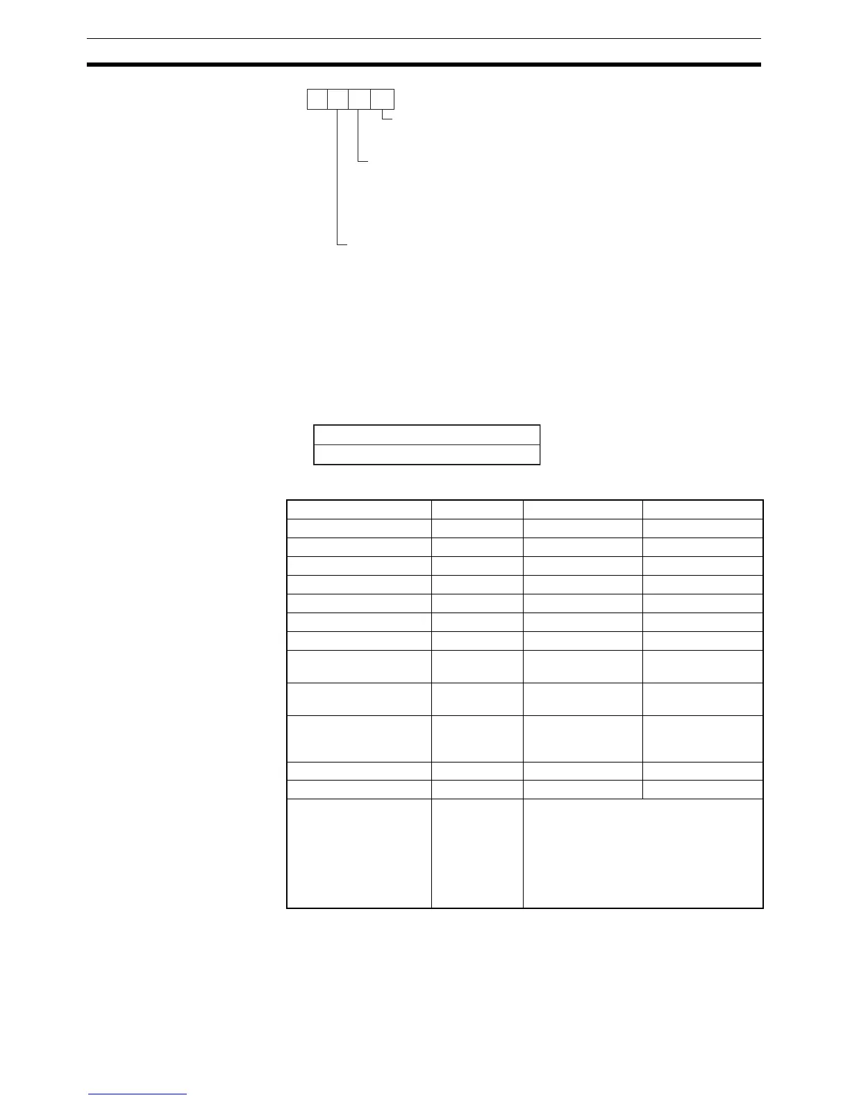
C1
0
Conversion Type
0 hex: Frequency to speed
1 hex: Counter PV to total revolutions
(When Conversion Type is "Frequency to speed")
Pulse Frequency Calculation Method
0 hex: Standard calculation method
1 hex: High-frequency calculation method, 10-ms sampling
2 hex: High-frequency calculation method, 100-ms sampling
3 hex: High-frequency calculation method, 1,000-ms sampling
(When Conversion Type is "Frequency to speed")
Speed Unit
0 hex: r/min
1 hex: r/s
2 hex: r/h
D
D+1
015
Conversion result (Rightmost 4 digits)
Conversion result (Leftmost 4 digits)
Area C1 C2 D
CIO Area --- CIO 0 to CIO 6143 CIO 0 to CIO 6142
Work Area --- W0 to W511 W0 to W510
Holding Bit Area --- H0 to H511 H0 to H510
Auxiliary Bit Area --- A448 to A959 A448 to A958
Timer Area --- T0000 to T4095 T0000 to T4094
Counter Area --- C0000 to C4095 C0000 to C4094
DM Area --- D0 to D32767 D0 to D32766
Indirect DM addresses
in binary
--- @ D0 to
@ D32767
@ D0 to
@ D32767
Indirect DM addresses
in BCD
--- *D0 to *D32767 *D0 to *D32767
Constants See descrip-
tion of oper-
and.
--- ---
Data Registers --- --- ---
Index Registers --- --- ---
Indirect addressing
using Index Registers
--- ,IR0 to ,IR15
–2048 to +2047 ,IR0 to
–2048 to +2047 ,IR15
DR0 to DR15, IR0 to IR15
,IR0+(++) to ,IR15+(++)
,–(– –)IR0 to, –(– –)IR15