4
Programming Concepts Section 1-1
1-1-2 Basic Information on Instructions
Programs consist of instructions. The conceptual structure of the inputs to and
outputs from an instruction is shown in the following diagram.
Power Flow The power flow is the execution condition that is used to control the execute
and instructions when programs are executing normally. In a ladder program,
power flow represents the status of the execution condition.
Input Instructions
• Load instructions indicate a logical start and outputs the execution condi-
tion.
• Intermediate instructions input the power flow as an execution condition
and output the power flow to an intermediate or output instruction.
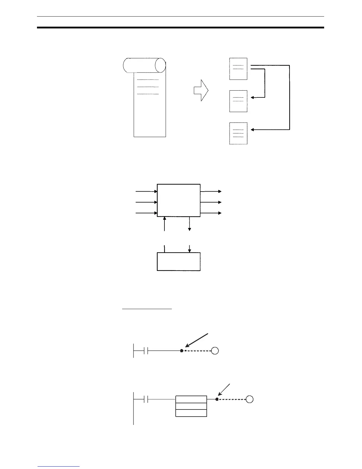
Earlier program:
Like a scroll
CP-series program:
Like a series of cards that can be activated
or deactivated by other cards.
Activated Deactivated
Flags
Instruction
Flag
Power flow (P.F., execution condition)
Instruction condition
Power flow (P.F., execution condition)
*
1
Instruction condition
*
2
Operands
(sources)
Operands
(destinations)
Memory
*1: Input instructions only.
*2: Not output for all instructions.
Outputs the
execution condition.
=
D0
#1215
Outputs the
execution condition.