xxxii
Conformance to EC Directives 6
When switching a load with a high inrush current such as an incandescent
lamp, suppress the inrush current as shown below.
6-5 Conditions for Meeting EMC Directives when Using CP1, CP-
series, or CPM1A Relay Expansion I/O Units
EN 61131-2 immunity testing conditions when using the CP1W-40EDR,
CPM1A-40EDR, CP1W-16ER or CPM1A-16ER with an CP1W-CN811 I/O
Connecting Cable are given below.
Recommended Ferrite Core
Ferrite Core (Data Line Filter): 0443-164151 manufactured by Nisshin Electric
Minimum impedance: 90 Ω at 25 MHz, 160 Ω at 100 MHz
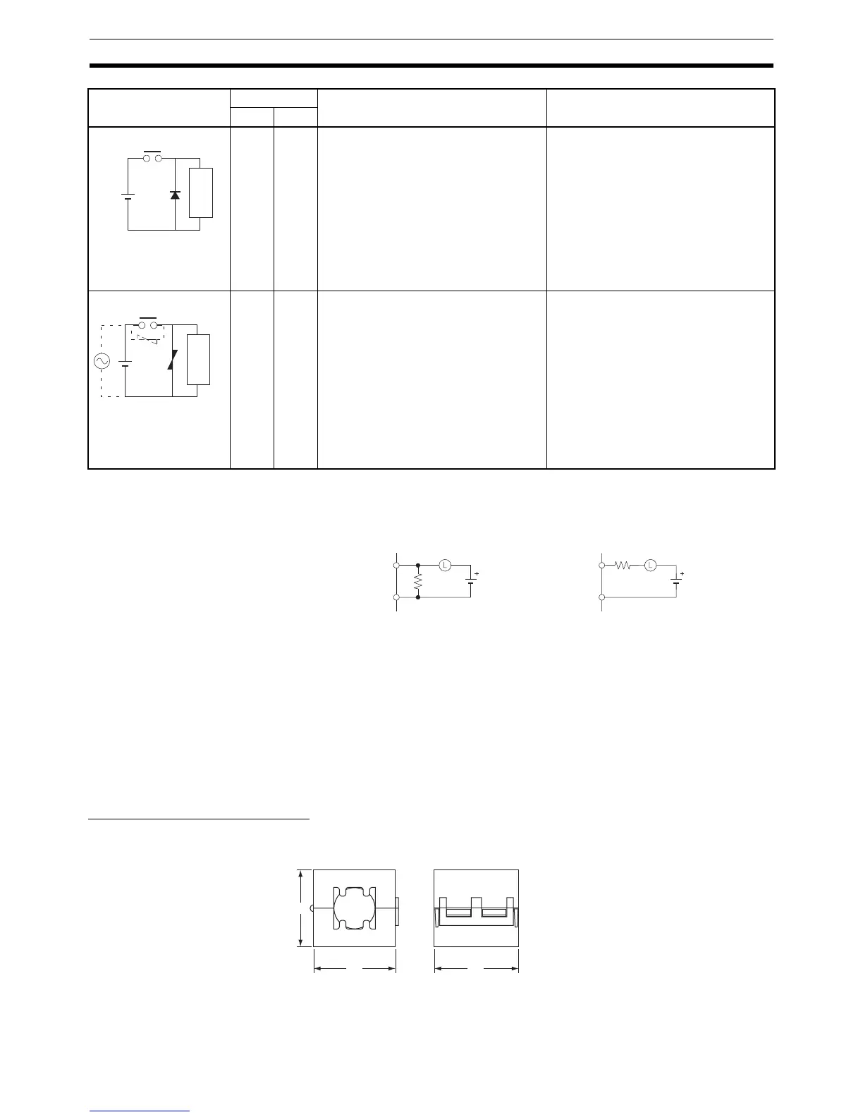
No Yes The diode connected in parallel with
the load changes energy accumulated
by the coil into a current, which then
flows into the coil so that the current will
be converted into Joule heat by the
resistance of the inductive load.
This time lag, between the moment the
circuit is opened and the moment the
load is reset, caused by this method is
longer than that caused by the CR
method.
The reversed dielectric strength value
of the diode must be at least 10 times
as large as the circuit voltage value.
The forward current of the diode must
be the same as or larger than the load
current.
The reversed dielectric strength value
of the diode may be two to three times
larger than the supply voltage if the
surge protector is applied to electronic
circuits with low circuit voltages.
Yes Yes The varistor method prevents the impo-
sition of high voltage between the con-
tacts by using the constant voltage
characteristic of the varistor. There is
time lag between the moment the cir-
cuit is opened and the moment the load
is reset.
If the supply voltage is 24 or 48 V, insert
the varistor in parallel with the load. If
the supply voltage is 100 to 200 V,
insert the varistor between the con-
tacts.
---
Circuit Current Characteristic Required element
AC DC
Diode method
Power
supply
Inductive
load
Varistor method
Power
supply
Inductive
load
OUT
COM
R
OUT
COM
R
Countermeasure 1
Providing a dark current of
approx. one-third of the rated
value through an incandescent
Countermeasure 2
Providing a limiting resistor
lamp
30
32 33