706
High-speed Counter/Pulse Output Instructions Section 3-20
Note (1) Interrupt inputs 4 and 5 cannot be used in the CP1L L CPU Units with 14
I/O points.
(2) Interrupt inputs 6 and 7 cannot be used in the CP1H Y CPU Units or the
CP1L L CPU Units with 14 I/O points.
C: Control Data
The function of INI(880) is determined by the control data, C.
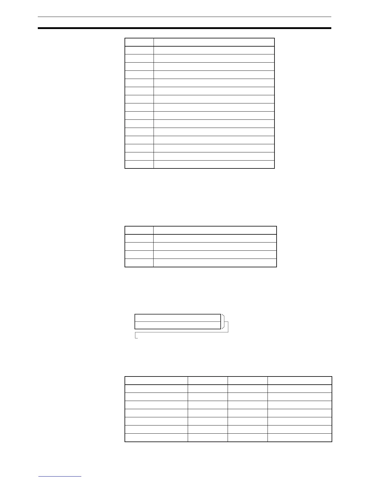
NV: First Word with New PV
NV and NV+1 contain the new PV when changing the PV.
If C is 0002 hex (i.e., when changing a PV), NV and NV+1 contain the new PV.
Any values in NV and NV+1 are ignored when C is not 0002 hex.
Operand Specifications
0011 hex High-speed counter 1
0012 hex High-speed counter 2
0013 hex High-speed counter 3
0020 hex Inverter positioning 0 (CP1L only)
0021 hex Inverter positioning 1 (CP1L only)
0100 hex Interrupt input 0 in counter mode
0101 hex Interrupt input 1 in counter mode
0102 hex Interrupt input 2 in counter mode
0103 hex Interrupt input 3 in counter mode
0104 hex Interrupt input 4 in counter mode (See note 1.)
0105 hex Interrupt input 5 in counter mode (See note 1.)
0106 hex Interrupt input 6 in counter mode (See note 2.)
0107 hex Interrupt input 7 in counter mode (See note 2.)
1000 hex PWM output 0
1001 hex PWM output 1
PPort
C INI(880) function
0000 hex Starts comparison.
0001 hex Stops comparison.
0002 hex Changes the PV.
0003 hex Stops pulse output.
S
S+1
0
15
For Pulse Output or High-speed Counter Input:
0000 0000 to FFFF FFFF hex
For Interrupt Input in Counter Mode:
0000 0000 to 0000 FFFF hex
Lower word of new PV
Upper word of new PV
Area P C NV
CIO Area --- --- CIO 0 to CIO 6142
Work Area --- --- W0 to W510
Holding Bit Area --- --- H0 to H510
Auxiliary Bit Area --- --- A448 to A958
Timer Area --- --- T0000 to T4094
Counter Area --- --- C0000 to C4094
DM Area --- --- D0 to D32766