101
Sequence Input Instructions Section 3-2
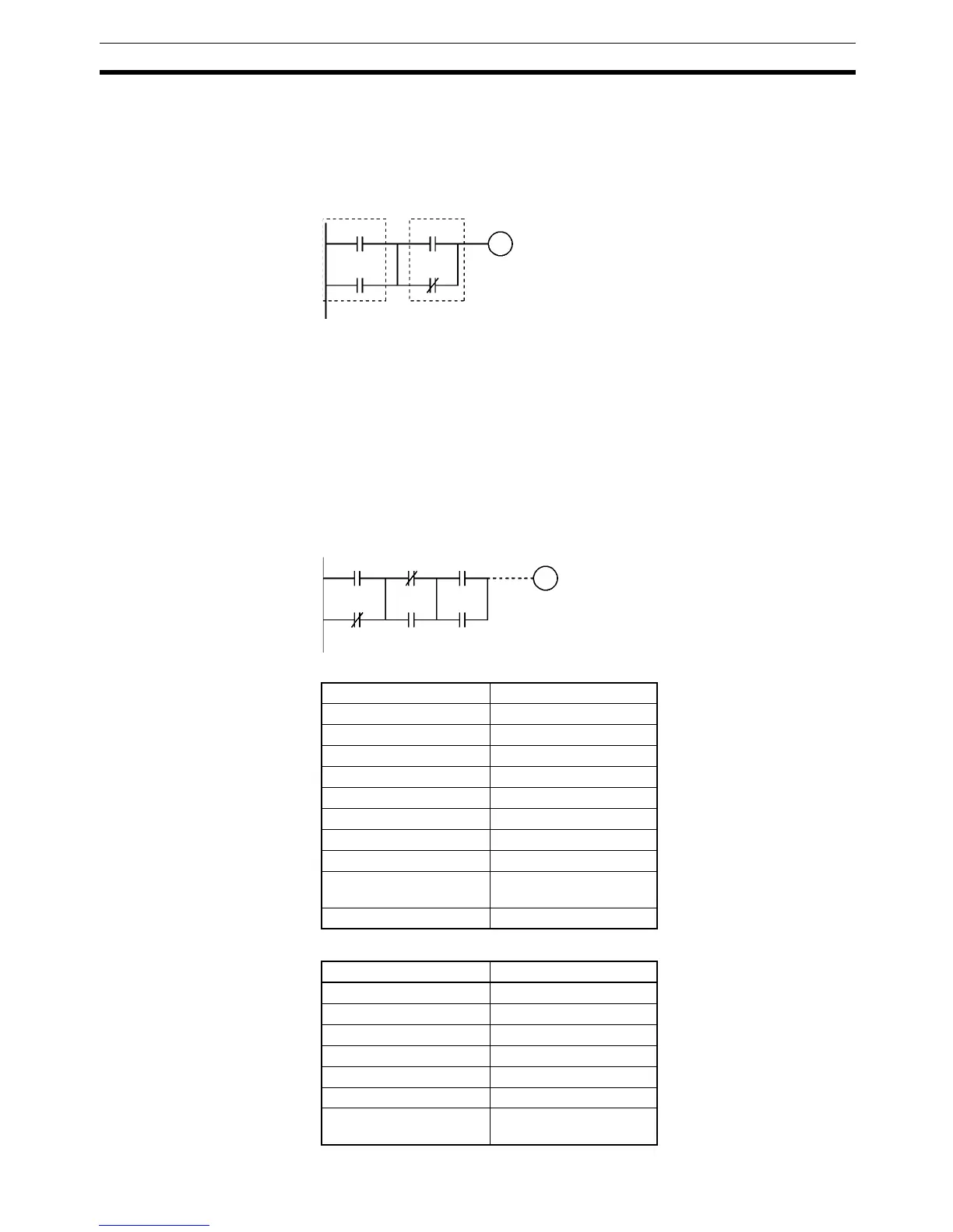
In the following diagram, the two logic blocks are indicated by dotted lines.
Studying this example shows that an ON execution condition will be produced
when either of the execution conditions in the left logic block is ON (i.e., when
either CIO 0.00 or CIO 0.01 is ON) and either of the execution conditions in
the right logic block is ON (i.e., when either CIO 0.02 is ON or CIO 0.03 is
OFF).
Flags There are no flags affected by this instruction.
Precautions Three or more logic blocks can be connected in series using this instruction to
first connect two of the logic blocks and then to connect the next and subse-
quent ones in order. It is also possible to continue placing this instruction after
three or more logic blocks and connect them together in series.
When a logic block is connected by AND LOAD or OR LOAD instructions, the
total number of AND LOAD/OR LOAD instructions must match the total num-
ber of LOAD/LOAD NOT instructions minus 1. If they do not match, a program
error will occur.
Example
Coding Example (1)
Coding Example (2)
0.00 0.02
0.01
0.03
100.00
Instruction Operand
LD 0.00
OR NOT 0.01
LD NOT 0.02
OR 0.03
AND LD ---
LD 0.04
OR 0.05
AND LD ---
.
.
.
.
OUT 100.00
Instruction Operand
LD 0.00
OR NOT 0.01
LD NOT 0.02
OR 0.03
LD 0.04
OR 0.05
.
.
.
.
0.00 0.02 0.04
100.00
0.01
0.03 0.05