197
Timer and Counter Instructions Section 3-5
Operand Specifications
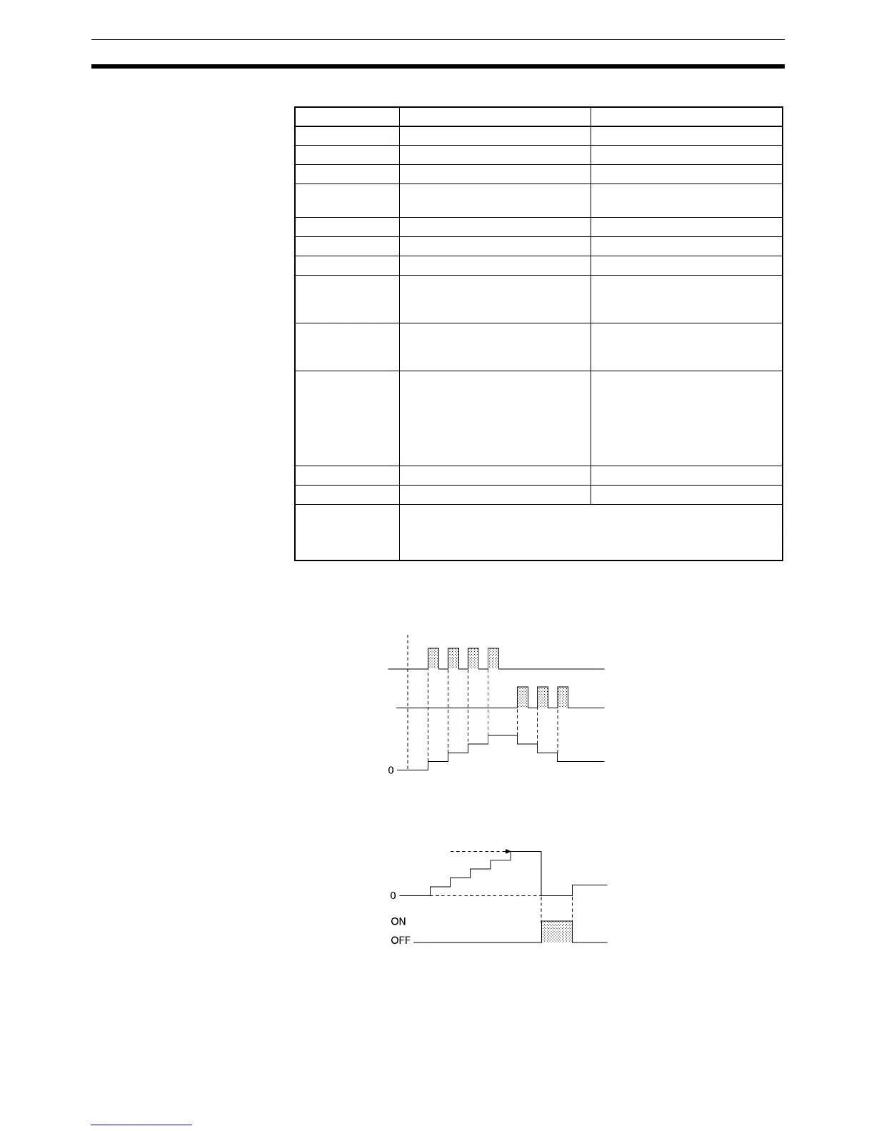
Description The counter PV is incremented by 1 every time that the increment input goes
from OFF to ON and it is decremented by 1 every time that the decrement
input goes from OFF to ON. The PV can fluctuate between 0 and the SV.
When incrementing, the Completion Flag will be turned ON when the PV is
incremented from the SV back to 0 and it will be turned OFF again when the
PV is incremented from 0 to 1.
Area N S
CIO Area --- CIO 0 to CIO 6143
Work Area --- W0 to W511
Holding Bit Area --- H0 to H511
Auxiliary Bit
Area
--- A0 to A959
Timer Area --- T0000 to T4095
Counter Area 0000 to 4095 (decimal) C0000 to C4095
DM Area --- D0 to D32767
Indirect DM
addresses in
binary
--- @ D0 to @ D32767
Indirect DM
addresses in
BCD
--- *D0 to *D32767
Constants --- BCD:
#0000 to 9999 (BCD)
“&” cannot be used.
Binary:
&0 to &65535 (decimal)
#0000 to #FFFF (hex)
Data Registers --- DR0 to DR15
Index Registers --- ---
Indirect address-
ing using Index
Registers
,IR0 to ,IR15
–2048 to +2047 ,IR0 to –2048 to +2047 ,IR15
DR0 to DR15, IR0 to IR15
Increment input
Counter PV
Decrement input
SV
+1
Counter PV
Completion Flag
 Loading...


