258
Data Movement Instructions Section 3-7
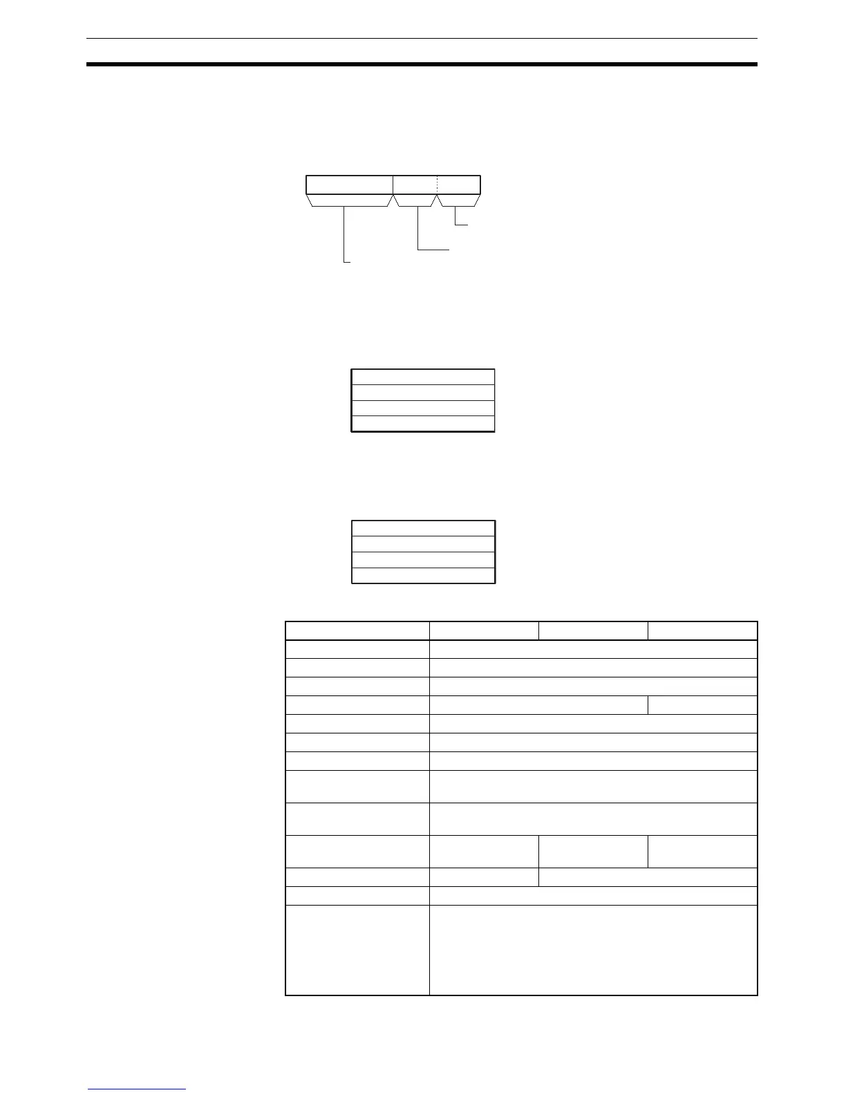
Operands C: Control Word
The first three digits of C indicate the first source digit (m), the number of dig-
its to transfer (n), and the first destination digit (l), as shown in the following
diagram.
S: First Source Word
Specifies the first source word. Bits are read from right to left, continuing with
consecutive words (up to S+16) when necessary.
D: First Destination Word
Specifies the first destination word. Bits are written from right to left, continu-
ing with consecutive words (up to D+16) when necessary.
Operand Specifications
15 8 037 4
C
l
nm
First bit in S (l
): 0 to F
First bit in D (m): 0 to 3
Number of digits (n):
00 to FF (0 to 255)
15 0
S
to to
S+15 max.
15 0
D
D+15 max.
to to
Area C S D
CIO Area CIO 0 to CIO 6143
Work Area W0 to W511
Holding Bit Area H0 to H511
Auxiliary Bit Area A0 to A959 A448 to A959
Timer Area T0000 to T4095
Counter Area C0000 to C4095
DM Area D0 to D32767
Indirect DM addresses
in binary
@ D0 to @ D32767
Indirect DM addresses
in BCD
*D0 to *D32767
Constants Specified values
only
--- ---
Data Registers DR0 to DR15 ---
Index Registers ---
Indirect addressing
using Index Registers
,IR0 to ,IR15
–2048 to +2047, IR0 to –2048 to +2047, IR15
DR0 to DR15, IR0 to IR15
,IR0+(++) to 5+(++)
,–(– –) IR0 to, –(– –) IR15