312
Data Shift Instructions Section 3-8
Operands C: Control Word
Operand Specifications
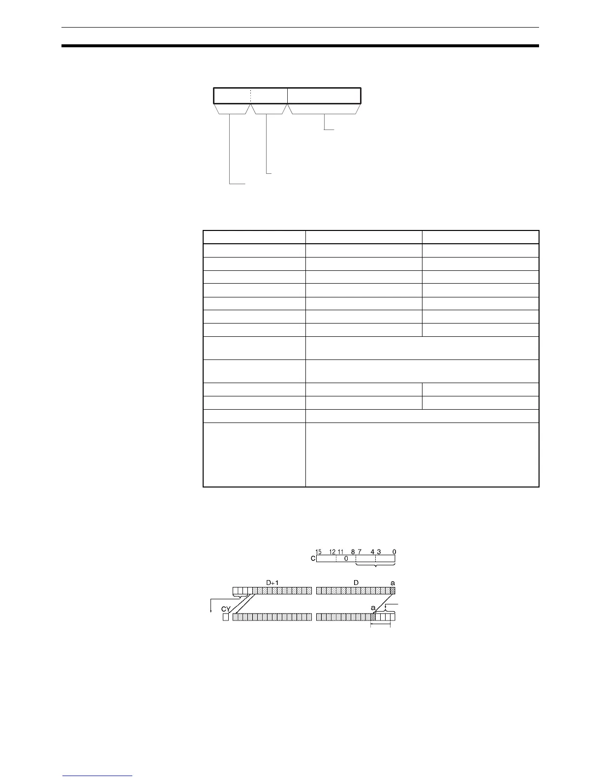
Description NSLL(582) shifts D and D+1 (the shift words) by the specified number of
binary bits (specified in C) to the left (from the rightmost bit to the leftmost bit).
Either zeros or the value of the rightmost bit will be placed into the specified
number of bits of the shift word starting from the rightmost bit.
15 8 011 712
C
0
No. of bits to shift: 00 to 20 Hex
Always 0.
Data shifted into register
0 Hex: 0 shifted in
8 Hex: Contents of rightmost bit shifted in
Area D C
CIO Area CIO 0 to CIO 6142 CIO 0 to CIO 6143
Work Area W0 to W510 W0 to W511
Holding Bit Area H0 to H510 H0 to H511
Auxiliary Bit Area A448 to A958 A0 to A959
Timer Area T0000 to T4094 T0000 to T4095
Counter Area C0000 to C4094 C0000 to C4095
DM Area D0 to D32766 D0 to D32767
Indirect DM addresses
in binary
@ D0 to @ D32767
Indirect DM addresses
in BCD
*D0 to *D32767
Constants --- Specified values only
Data Registers --- DR0 to DR15
Index Registers ---
Indirect addressing
using Index Registers
,IR0 to ,IR15
–2048 to +2047 ,IR0 to –2048 to +2047 ,IR15
DR0 to DR15, IR0 to IR15
,IR0+(++) to ,IR15+(++)
,–(– –)IR0 to, –(– –)IR15
Shift n-bits
Contents of "a" or "0" shifted in
N bits
Lost