439
Logic Instructions Section 3-12
If as a result of the AND, the leftmost bit of R+1 is 1, the Negative Flag will
turn ON.
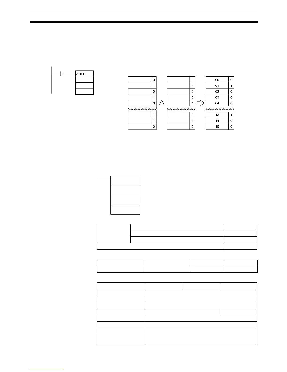
Examples When the execution condition CIO 0.00 is ON, the logical AND will be taken of
corresponding bits in CIO 1001, CIO 1000 and CIO 2001, CIO 2000 and the
results will be output to corresponding bits in D201 and D200.
3-12-3 LOGICAL OR: ORW(035)
Purpose Takes the logical OR of corresponding bits in single words of word data and/or
constants.
Ladder Symbol
Variations
Applicable Program Areas
Operand Specifications
S
1
: CIO 1000
S
1
+1: CIO 1001
S
2
: CIO 2000
S
2
+1: CIO 2001
D: D200
D+1: D201
0.00
1000
2000
D200
1000.00
1000.01
1000.02
1000.03
1000.04
1001.13
1001.14
1001.15
2000.00
2000.01
2000.02
2000.03
2000.04
2001.13
2001.14
2001.15
Note: The vertical arrow indicates lo
ical AND.
ORW(035)
I
1
I
2
R
I
1
: Input 1
I
2
: Input 2
R: Result word
Variations Executed Each Cycle for ON Condition ORW(035)
Executed Once for Upward Differentiation @ORW(035)
Executed Once for Downward Differentiation Not supported.
Immediate Refreshing Specification Not supported.
Block program areas Step program areas Subroutines Interrupt tasks
OK OK OK OK
Area I
1
I
2
R
CIO Area CIO 0 to CIO 6143
Work Area W0 to W511
Holding Bit Area H0 to H511
Auxiliary Bit Area A0 to A959 A448 to A959
Timer Area T0000 to T4095
Counter Area C0000 to C4095
DM Area D0 to D32767
Indirect DM addresses
in binary
@ D0 to @ D32767