24
Programming Concepts Section 1-1
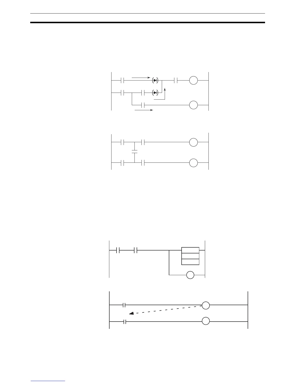
were inserted and coil R2 cannot be driven with contact D included. The
actual order of execution is indicated on the right with mnemonics. To
achieve operation without these imaginary diodes, the circuit must be re-
written. Also, circuit “b” power flow cannot be programmed directly and
must be rewritten.
In circuit “a,” coil R2 cannot be driven with contact D included.
In circuit “b,” contact E included cannot be written in a ladder diagram. The
program must be rewritten.
2. There is no limit to the number of I/O bits, work bits, timers, and other input
bits that can be used. Rungs, however, should be kept as clear and simple
as possible even if it means using more input bits to make them easier to
understand and maintain.
3. There is no limit to the number of input bits that can be connected in series
or in parallel in series or parallel rungs.
4. Two or more output bits can be connected in parallel.
5. Output bits can also be used as input bits.
A
B
AB
C D
CD
E
(1)
(6)
(2) ((3)) (4)
(9)
(7)
(10)
((8))
((5))
R1
R2
R1
R2
E
(6) AND B
(7) OUT R1
(8) LD TR0
(9) AND E
(10) OUT R2
(1) LD A
(2) LD C
(3) OUT TR0
(4) AND D
(5) OR LD
Circuit "a"
Signal flow
Order of execution (mnemonic)
Circuit " b"
0.00 0.05
102.00
TIM
0000
#100
102.00
102.00