576
Table Data Processing Instructions Section 3-16
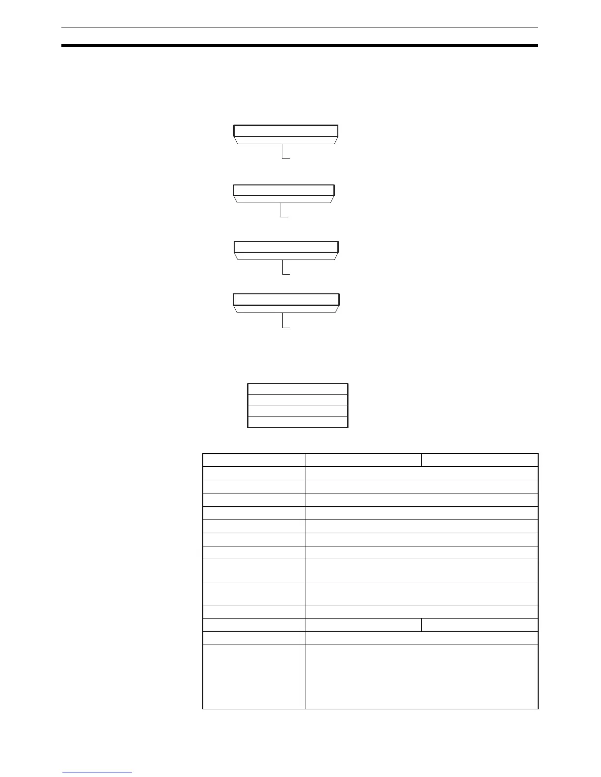
Operands TB through TB+3: Stack control words
The first four words of the stack contain the PLC memory address of the last
word in the stack and the stack pointer (the PLC memory address of the next
word to be overwritten by PUSH(632)).
TB+4 through TB+(N–1): Data storage region
The remainder of the stack is used to store data.
Operand Specifications
15 0
TB
15 0
TB+1
15 0
TB+2
15 0
TB+3
Stack
Stack pointer (rightmost 4 digits)
PLC memory address of the last
word in the stack (leftmost 4 digits)
PLC memory address of the last
word in the stack (rightmost 4 digits)
15 0
---
TB+4
TB+(N–1)
Data storage region
Area TB D
CIO Area CIO 0 to CIO 6143
Work Area W0 to W511
Holding Bit Area H0 to H511
Auxiliary Bit Area A448 to A959
Timer Area T0000 to T4095
Counter Area C0000 to C4095
DM Area D0 to D32767
Indirect DM addresses
in binary
@ D0 to @ D32767
Indirect DM addresses
in BCD
*D0 to *D32767
Constants ---
Data Registers --- DR0 to DR15
Index Registers ---
Indirect addressing
using Index Registers
,IR0 to ,IR15
–2048 to +2047 ,IR0 to –2048 to +2047 ,IR15
DR0 to DR15, IR0 to IR15
,IR0+(++) to ,IR15+(++)
,–(– –)IR0 to, –(– –)IR15