581
Table Data Processing Instructions Section 3-16
Operands N: Table number
Indicates the table number. N must be between 0 and 15.
R: Record number
Indicates the record number of the desired record. R must be 0000 to FFFE
hexadecimal (0 to 65,534). Record numbers begin with 0, so the valid record
numbers are 0 to NR–1 for a table with NR records.
D: Destination Index Register
Indicates the desired Index Register. D must be IR0 to IR15.
Operand Specifications
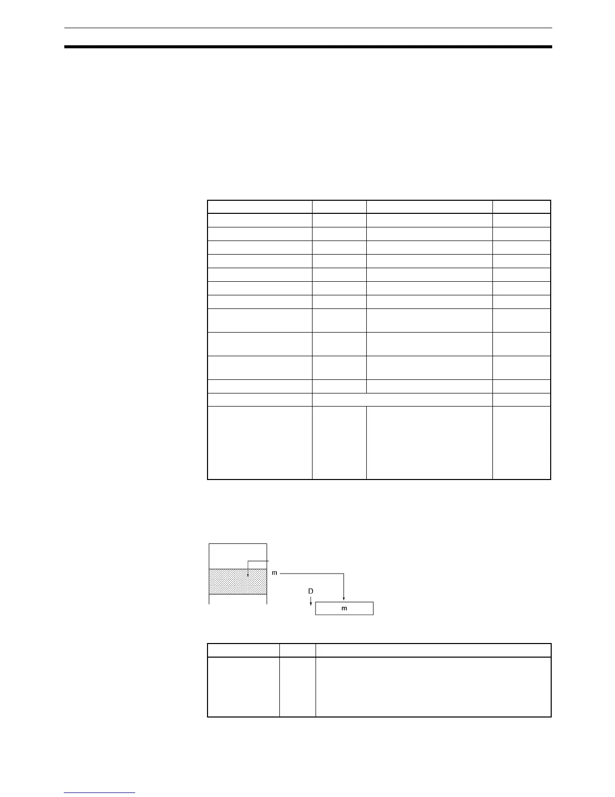
Description SETR(635) stores the PLC memory address of the first word of the specified
record in the specified Index Register. The following diagram shows the basic
operation of SETR(635).
Flags
Precautions The record table must be defined in advance with DIM(631).
Area N R D
CIO Area --- CIO 0 to CIO 6143 ---
Work Area --- W0 to W511 ---
Holding Bit Area --- H0 to H511 ---
Auxiliary Bit Area --- A0 to A959 ---
Timer Area --- T0000 to T4095 ---
Counter Area --- C0000 to C4095 ---
DM Area --- D0 to D32767 ---
Indirect DM addresses
in binary
--- @ D0 to @ D32767 ---
Indirect DM addresses
in BCD
--- *D0 to *D32767 ---
Constants 0 to 15 #0000 to #FFFE (binary) or
&0 to 65534
---
Data Registers --- DR0 to DR15 ---
Index Registers --- IR0 to IR15
Indirect addressing
using Index Registers
--- ,IR0 to ,IR15
–2048 to +2047 ,IR0 to –2048
to +2047 ,IR15
DR0 to DR15, IR0 to IR15
,IR0+(++) to ,IR15+(++)
,– (– –)IR0 to, – (– –)IR15
---
R
IR@
SETR(635) writes the PLC memory address (m)
of the first word of record R to Index Register D.
PLC memory
address
Table number (N)
Record
number (R)
Name Label Operation
Error Flag ER ON if the specified table number (N) has not been defined
with DIM(631).
ON if the specified record number (R) exceeds the high-
est record number in the table (NR–1).
OFF in all other cases.