653
Data Control Instructions Section 3-17
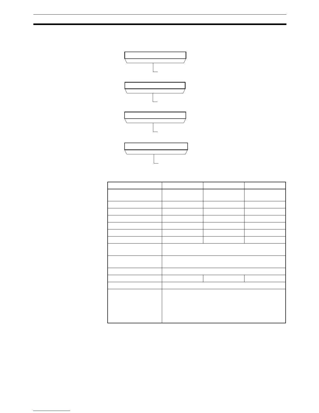
Operands The contents of the four words starting with the first parameter word (P1) are
shown in the following diagram.
Operand Specifications
Description SCL(194) is used to convert the unsigned binary data contained in the source
word S into unsigned BCD data and place the result in the result word R
according to the linear function defined by points (As, Ad) and (Bs, Bd). The
address of the first word containing the coordinates of points (As, Ar) and (Bs,
Br) is specified for the first parameter word P1. These points define by 2 val-
ues (As and Bs) before scaling and 2 values (Ar and Br) after scaling.
P1
P1+1
P1+2
P1+3
15 0
15
0
15
0
15
0
Scaled value for point A (Ar)
0000 to 9999 (4-digit BCD)
Unscaled value for point A (As)
0000 to FFFF (binary)
Scaled value for point B (Br)
0000 to 9999 (4-digit BCD)
Unscaled value for point B (Bs)
0000 to FFFF (binary)
Area S P1 R
CIO Area CIO 0 to
CIO 6143
CIO 0 to
CIO 6140
CIO 0 to
CIO 6143
Work Area W0 to W511 W0 to W508 W0 to W511
Holding Bit Area H0 to H511 H0 to H508 H0 to H511
Auxiliary Bit Area A0 to A959 A0 to A956 A448 to A959
Timer Area T0000 to T4095 T0000 to T4092 T0000 to T4095
Counter Area C0000 to C4095 C0000 to C4092 C0000 to C4095
DM Area D0 to D32767 D0 to D32764 D0 to D32767
Indirect DM addresses
in binary
@ D0 to @ D32767
Indirect DM addresses
in BCD
*D0 to *D32767
Constants ---
Data Registers DR0 to DR15 --- DR0 to DR15
Index Registers ---
Indirect addressing
using Index Registers
,IR0 to ,IR15
–2048 to +2047 ,IR0 to –2048 to +2047 ,IR15
DR0 to DR15, IR0 to IR15
,IR0+(++) to ,IR15+(++)
,–(– –)IR0 to, –(– –)IR15
 Loading...


