694
Interrupt Control Instructions Section 3-19
Operand Specifications
Description MSKS(690) controls input interrupts and scheduled interrupts. The value of N
identifies the interrupt.
Input Interrupts: N = 100 to 107, 110 to 117, or 6 to 13
• MSKS(690) specifies whether interrupts are generated when the interrupt
input turns ON or turns OFF and whether to mask or unmask the inter-
rupt. If the specification is omitted, interrupts are generated when the
interrupt input turns ON.
• When an interrupt is unmasked, either direct mode or counter mode
(incrementing or decrementing) is specified. Refer to Interrupt Functions
in the CP1H or CP1L Operation Manual for details.
• Any interrupts that are masked will be cleared when the interrupt is
unmasked or the ON/OFF specification for generating interrupts is
changed.
Scheduled Interrupt: N = 4 or 14
• MSKS(690) specifies the interrupt interval and starts the internal timer.
The interrupt interval also depends on the setting of the Scheduled Inter-
rupt Interval in the PLC Setup.
• The internal timer can be reset or not reset depending on the operands
for MSKS(690).
• When the internal timer is reset, timing will start after the timer is reset
and scheduled interrupt will occur at the interval specified in S from the
time MSKS(690) is executed.
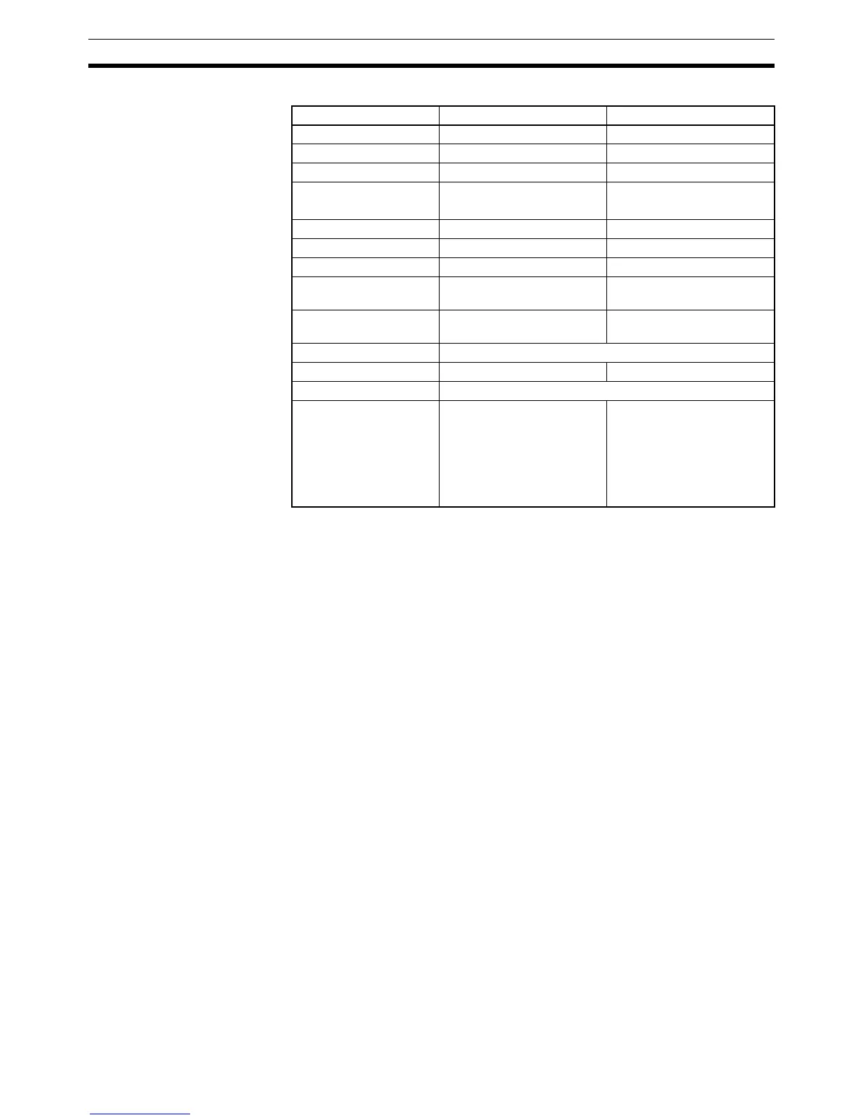
Area N S
CIO Area --- CIO 0 to CIO 6143
Work Area --- W0 to W511
Holding Bit Area --- H0 to H511
Auxiliary Bit Area --- A0 to A447
A448 to A959
Timer Area --- T0000 to T4095
Counter Area --- C0000 to C4095
DM Area --- D0 to D32767
Indirect DM addresses
in binary
--- @ D0 to @ 32767
Indirect DM addresses
in BCD
--- *D0 to *D32767
Constants Specified values only
Data Registers --- DR0 to DR15
Index Registers ---
Indirect addressing
using Index Registers
--- ,IR0 to ,IR15
–2048 to +2047, IR0 to
–2048 to +2047, IR15
DR0 to DR15, IR0 to IR15
,IR0+(++) to ,IR15+(++)
,–(– –) IR0 to, –(– –) IR15