698
Interrupt Control Instructions Section 3-19
Operand Specifications
Description The value of N identifies the interrupt.
Input Interrupts: N = 100 to 107, 110 to 117, or 6 to 13
The mask status or the trigger specification (ON or OFF) specified with N is
stored in D.
Scheduled Interrupt: N = 4 or 14
The scheduled interrupt interval (set value) or the present value of the internal
timer specified with N is stored in D as a hexadecimal value. The units for the
scheduled interrupt interval is specified in the PLC Setup as the Scheduled
Interrupt Interval.
Flags
Precautions MSKR(692) can be executed in the main program or in interrupt tasks.
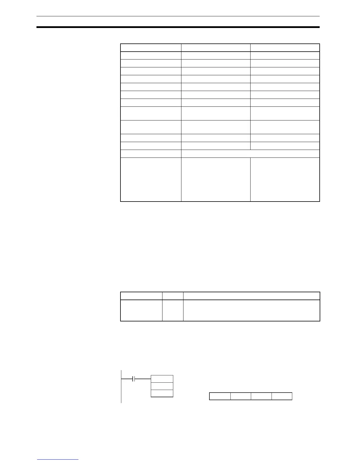
Examples Input Interrupts
When W0.00 turns ON in the following example, the mask status of input
interrupt 0 (CIO 0.00) is stored in D100. The value in the example (0003) says
that the interrupt is unmasked in incrementing counter mode.
Area N D
CIO Area --- CIO 0 to CIO 6143
Work Area --- W0 to W511
Holding Bit Area --- H0 to H511
Auxiliary Bit Area --- A448 to A959
Timer Area --- T0000 to T4095
Counter Area --- C0000 to C4095
DM Area --- D0 to D32767
Indirect DM addresses
in binary
--- @ D0 to @ D32767
Indirect DM addresses
in BCD
--- *D0 to *D32767
Constants Specified values only ---
Data Registers --- DR0 to DR15
Index Registers ---
Indirect addressing
using Index Registers
--- ,IR0 to ,IR15
–2048 to +2047, IR0 to
–2048 to +2047, IR15
DR0 to DR15, IR0 to IR15
,IR0+(++) to ,IR15+(++)
,–(– –) IR0 to, –(– –) IR15
Name Label Operation
Error Flag ER ON if N is not within the specified range of 0 to 5 (0 to 15
for the CJ1M).
OFF in all other cases.
MSKR
100
D100
W0.00
N
D
D100
015
8 7
3000