711
High-speed Counter/Pulse Output Instructions Section 3-20
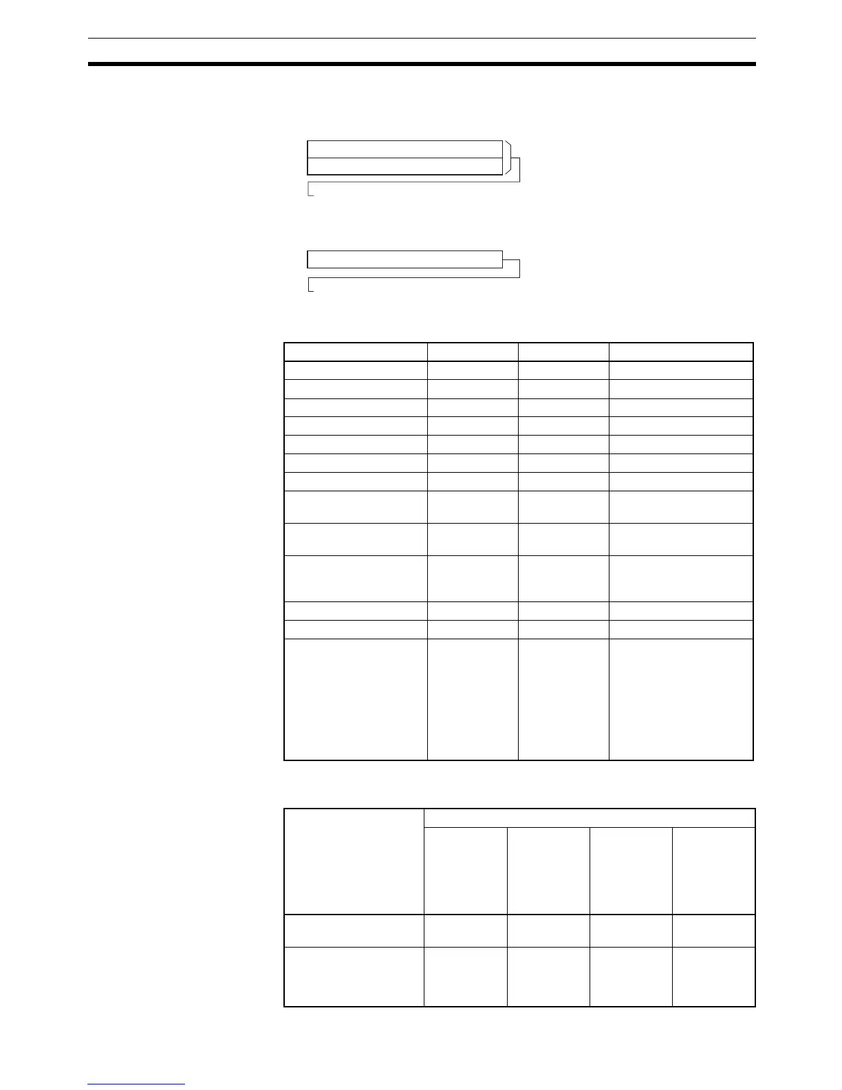
D: First Destination Word
The PV is output to D or to D and D+1.
Operand Specifications
Description PRV(881) reads the data specified in C for the port specified in P. The possi-
ble combinations of data and ports are shown in the following table.
D
D+1
0
15
DPV
0
15
Lower word of PV
Upper word of PV
2-word PV
Pulse output PV, high-speed counter input PV,
high-speed counter input frequency for high-speed counter input 0
1-word PV
Interrupt input PV in counter mode, status, range comparison results
Area P C D
CIO Area --- --- CIO 0 to CIO 6142
Work Area --- --- W0 to W510
Holding Bit Area --- --- H0 to H510
Auxiliary Bit Area --- --- A448 to A958
Timer Area --- --- T0000 to T4094
Counter Area --- --- C0000 to C4094
DM Area --- --- D0 to D32766
Indirect DM addresses
in binary
--- --- @ D0 to @ D32766
Indirect DM addresses
in BCD
--- --- *D0 to *D32766
Constants See descrip-
tion of oper-
and.
See descrip-
tion of oper-
and.
---
Data Registers --- --- ---
Index Registers --- --- ---
Indirect addressing
using Index Registers
--- --- ,IR0 to ,IR15
–2048 to +2047 ,IR0 to
–2048 to +2047 ,IR15
DR0 to DR15, IR0 to
IR15
,IR0+(++) to ,IR15+(++)
,–(– –)IR0 to, –(– –)IR15
P: Port specifier C: Control data
0000 hex:
Read PV
0001 hex:
Read status
0002 hex:
Read range
comparison
results
0003 hex:
Pulse output
read high-
speed
counter
frequency
0000 to 0003 hex:
Pulse output
OK OK Not allowed. OK
0010 to 0013 hex:
High-speed counter
input
OK OK OK OK (high-
speed
counter 0
only)
 Loading...


