740
High-speed Counter/Pulse Output Instructions Section 3-20
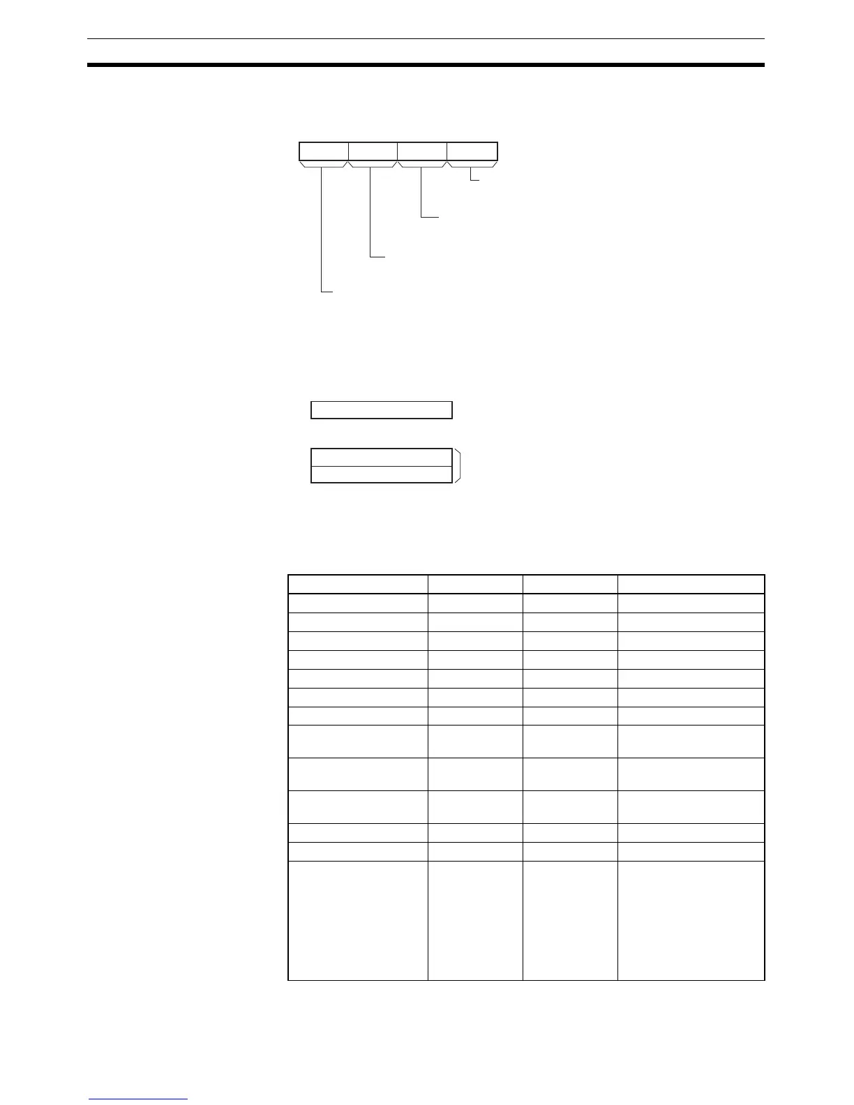
M: Output Mode
The content of M specifies the parameters for the pulse output as follows:
S: First Word of Settings Table
The content of S to S+2 controls the pulse output as shown in the following
diagrams.
Operand Specifications
03478
111215
M
Mode
0 hex: Continuous mode
1 hex: Independent mode
Direction
0 hex: CW
1 hex: CCW
Pulse output method (See note.)
0 hex: CW/CCW
1 hex: Pulse + direction
Always 0 hex.
Note: Use the same pulse output method when using both pulse outputs 0 and 1 (CP1H only).
S+1
S+2
S
0
15
Lower word with target frequency
Upper word with target frequency
0 to 1,000,000 Hz (See note.)
(0000 0000 to 000F 4240 hex)
Specify the frequency after acceleration in Hz.
Acceleration/deceleration rate
1 to 65,535 Hz (0001 to FFFF hex)
Specify the increase or decrease in the frequency per pulse control period (4 ms).
Note: The maximum frequency that can be specified
depends on the model and pulse output support.
Refer to the CP1H Operation Manual.
Area P M S
CIO Area --- --- CIO 0 to CIO 6141
Work Area --- --- W0 to W509
Holding Bit Area --- --- H0 to H509
Auxiliary Bit Area --- --- A448 to A957
Timer Area --- --- T0000 to T4093
Counter Area --- --- C0000 to C4093
DM Area --- --- D0 to D32765
Indirect DM addresses
in binary
--- --- @ D0 to @ D32767
Indirect DM addresses
in BCD
--- --- *D0 to *D32767
Constants See description
of operand.
See description
of operand.
---
Data Registers --- --- ---
Index Registers --- --- ---
Indirect addressing
using Index Registers
--- --- ,IR0 to ,IR15
–2048 to +2047 ,IR0 to
–2048 to +2047 ,IR15
DR0 to DR15, IR0 to
IR15
,IR0+(++) to ,IR15+(++)
,–(– –)IR0 to, –(– –)IR15