750
High-speed Counter/Pulse Output Instructions Section 3-20
F: Frequency
F specifies the frequency of the pulse output. The value of F must be in one of
the following ranges.
• When specified in 0.1 Hz units: 0001 to FFFF hex (0.1 and 6,553.5 Hz)
• When specified in 1 Hz units (CPL1 only): 0001 to 8020 hex (1 to 32,800
Hz)
The accuracy of the PMW(891) waveform that is actually output (ON duty
+5%/
−0%) applies only to 0.1 to 1,000.0 Hz due to limitations in the output cir-
cuits.
D: Duty Factor
D specifies the duty factor of the pulse output, i.e., the percentage of time that
the output is ON. The value of D must be in one of the following ranges.
• When specified in 0.1% units: 0000 to 03E8 hex (0.0% and 100.0%)
• When specified in 1% units: 0000 to 0064 hex (0% and 100%)
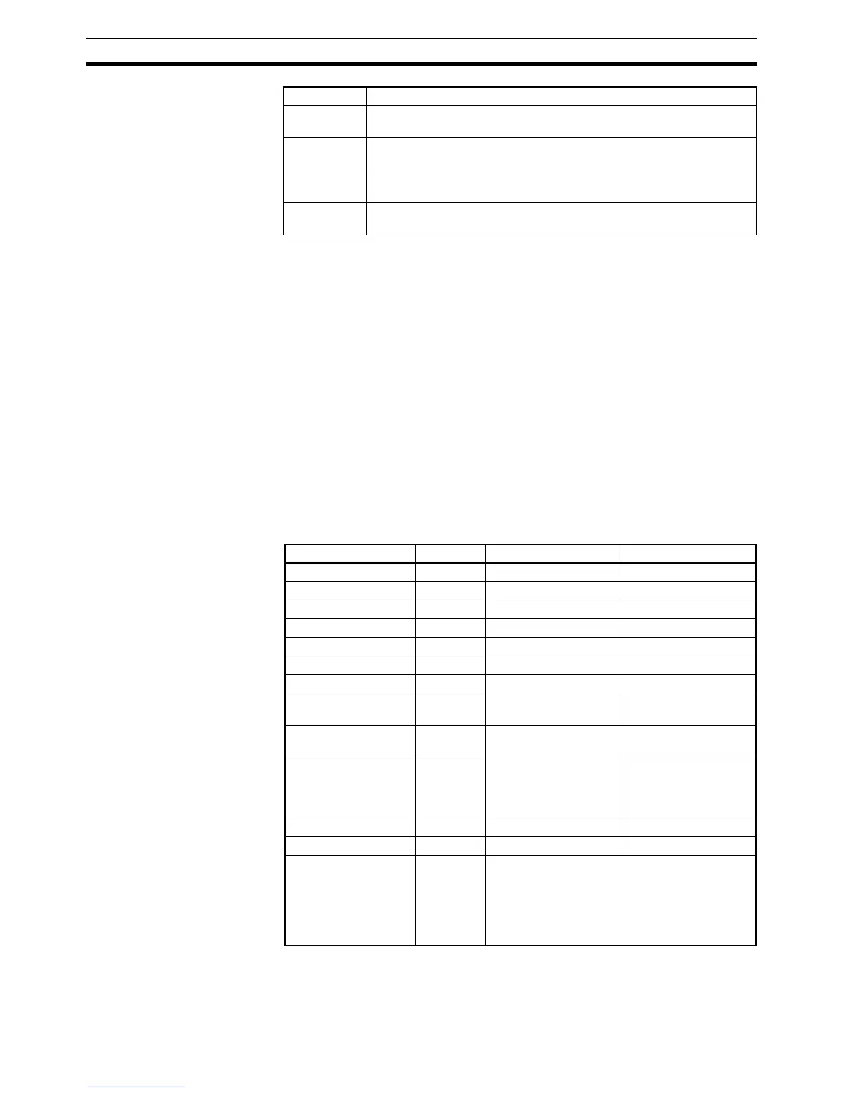
Operand Specifications
0100 hex Pulse output 0 (CP1L only)
Duty factor in increments of 1%, Frequency in increments of 1 Hz
0101 hex Pulse output 1 (CP1L only)
Duty factor in increments of 1%, Frequency in increments of 1 Hz
0100 hex Pulse output 0 (CP1L only)
Duty factor in increments of 0.1%, Frequency in increments of 1 Hz
1101 hex Pulse output 1 (CP1L only)
Duty factor in increments of 0.1%, Frequency in increments of 1 Hz
PPort
Area P F D
CIO Area --- CIO 0 to CIO 6143 CIO 0 to CIO 6143
Work Area --- W0 to W511 W0 to W511
Holding Bit Area --- H0 to H511 H0 to H511
Auxiliary Bit Area --- A448 to A959 A448 to A959
Timer Area --- T0000 to T4095 T0000 to T4095
Counter Area --- C0000 to C4095 C0000 to C4095
DM Area --- D0 to D32767 D0 to D32767
Indirect DM
addresses in binary
--- @ D0 to @ D32767 @ D0 to @ D32767
Indirect DM
addresses in BCD
--- *D0 to *D32767 *D0 to *D32767
Constants See
descrip-
tion of
operand.
0000 to FFFF hex 0000 to 03E8 hex
Data Registers --- DR0 to DR15 DR0 to DR15
Index Registers --- --- ---
Indirect addressing
using Index Registers
--- ,IR0 to ,IR15
–2048 to +2047 ,IR0 to –2048 to +2047 ,IR15
DR0 to DR15, IR0 to IR15
,IR0+(++) to ,IR15+(++)
,–(– –)IR0 to, –(– –)IR15