780
Basic I/O Unit Instructions Section 3-22
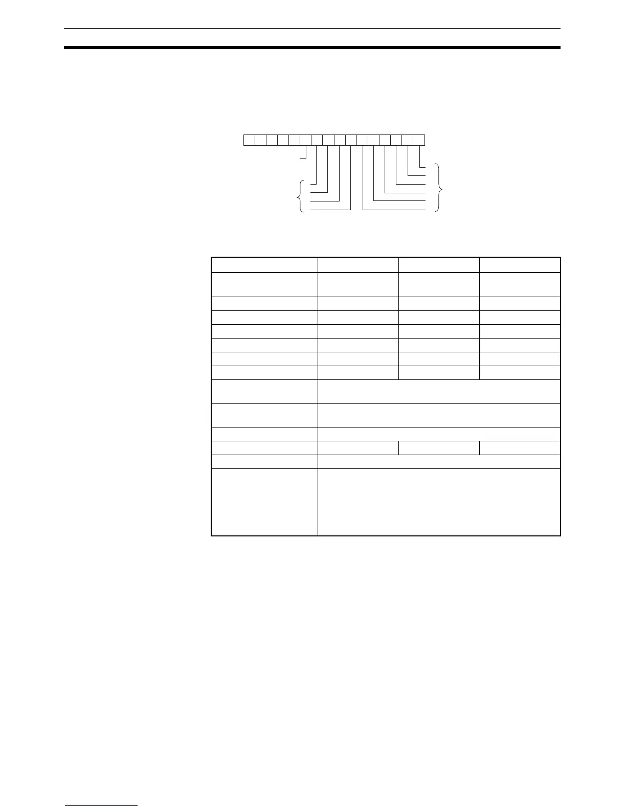
D
2
: Key Input Word
Bits 00 to 10 of D
2
indicate key inputs. When one of the keys on the keypad (0
to 9) has been pressed, the corresponding bit of D
2
(0 to 9) is turned ON. Bit
10 of D
2
will be ON while any key is being pressed.
Operand Specifications
Description TKY(211) reads numeric data from input word I, which is allocated to a ten-
key keypad connected to an Input Unit, and stores up to 8 digits of BCD data
in register words D
1
and D
1
+1. In addition, each time that a key is pressed,
the corresponding bit in D
2
(0 to 9) will be turned ON and remains ON until
another key is pressed. Bit 10 of D
2
will be ON while any key is being pressed
and OFF when no key is being pressed.
The two-word register in D
1
and D
1
+1 operates as an 8-digit shift register.
When a key is pressed on the ten-key keypad, the corresponding BCD digit is
shifted into the least significant digit of D
1
. The other digits of D
1
, D
1
+1 are
shifted left and the most significant digit of D
1
+1 is lost.
When executed, TKY(211) begins reading the key input data from the first
cycle, regardless of the point at which the last instruction was stopped.
When one of the keypad keys is being pressed, input from the other keys is
disabled.
0123456789101112131415
−−−−−
D2
0
1
2
3
4
5
9
8
7
6
ON when any
key is pressed.
ON when the corre-
sponding key is press-
ed. (Remains on until
another key is pressed.)
ON when the corre-
sponding key is press-
ed. (Remains on until
another key is pressed.)
Area I D
1
D
2
CIO Area CIO 0 to
CIO 6143
CIO 0 to
CIO 6142
CIO 0 to
CIO 6143
Work Area W0 to W511 W0 to W510 W0 to W511
Holding Bit Area H0 to H511 H0 to H510 H0 to H511
Auxiliary Bit Area A0 to A959 A448 to A958 A448 to A959
Timer Area T0000 to T4095 T0000 to T4094 T0000 to T4095
Counter Area C0000 to C4095 C0000 to C4094 C0000 to C4095
DM Area D0 to D32767 D0 to D32766 D0 to D32767
Indirect DM addresses
in binary
@ D0 to @ D32767
Indirect DM addresses
in BCD
*D0 to *D32767
Constants ---
Data Registers DR0 to DR15 --- DR0 to DR15
Index Registers ---
Indirect addressing
using Index Registers
,IR0 to ,IR15
–2048 to +2047 ,IR0 to –2048 to +2047 ,IR15
DR0 to DR15, IR0 to IR15
,IR0+(++) to ,IR15+(++)
,–(– –)IR0 to, –(– –)IR15