783
Basic I/O Unit Instructions Section 3-22
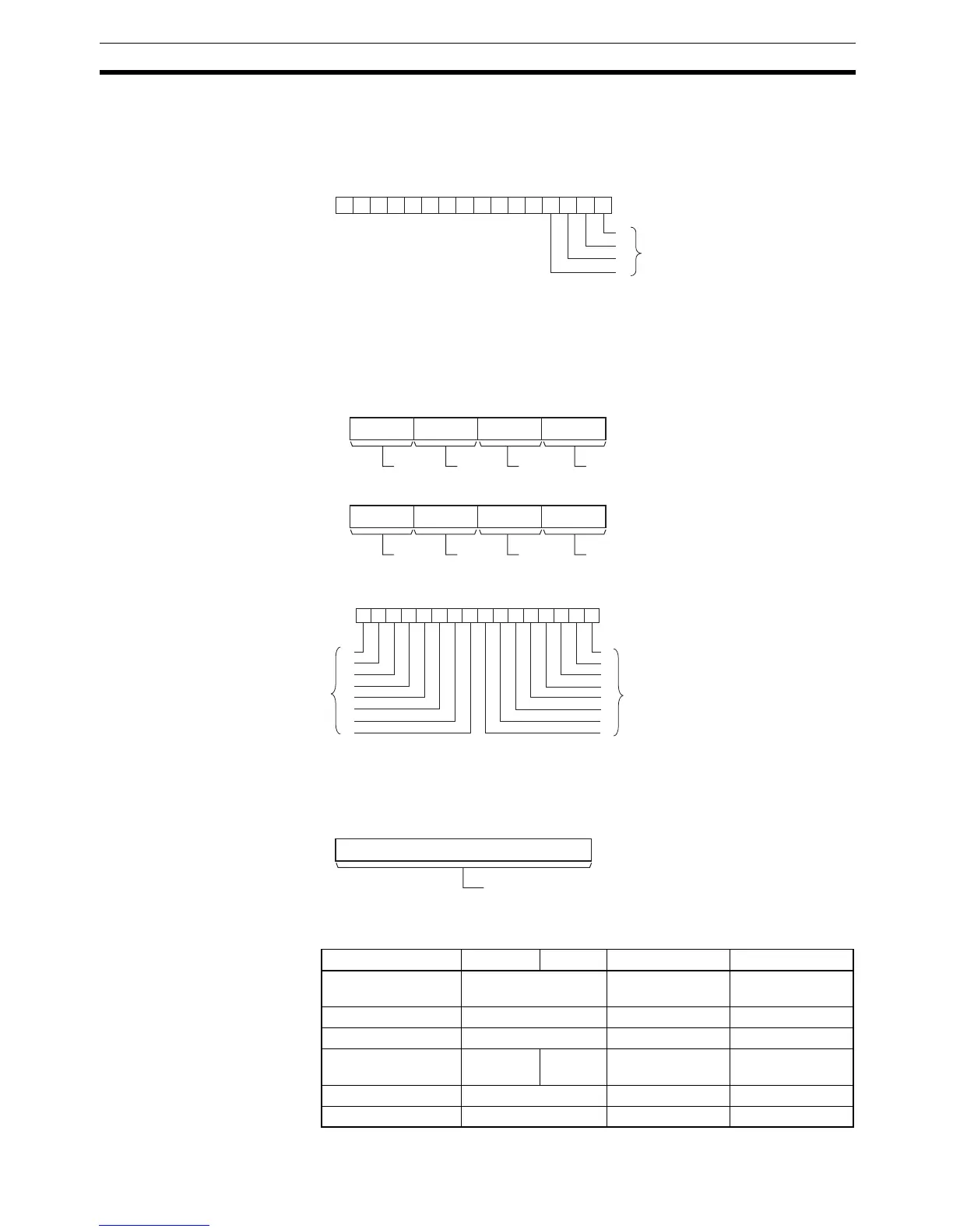
O: Output Word (Selection Signal Outputs)
Specify the output word allocated to the Output Unit and connect the hexa-
decimal keypad’s selection signals to the Output Unit as shown in the follow-
ing diagram.
D: First Register Word
Specifies the leading word address where the hexadecimal keypad’s numeric
input (up to 8 digits) will be stored. (In addition, each time that a key is
pressed, the corresponding bit in D+2 (0 to F) will be turned ON and remains
ON until another key is pressed.)
C: System Word
Specifies a work word used by the instruction. This word cannot be used in
any other application.
Operand Specifications
0123456789101112131415
−−−−−−−−−−−−
O
0
1
2
3
Bits 00 to 03 correspond to
Output Unit outputs 0 to 3.
D
815 1211 0347
D+1
815 1211 0347
0123456789101112131415
D+2
0
1
2
3
4
5
6
7
15
14
13
12
11
10
9
8
Digit 1
Digit 2
Digit 3
Digit 4
Digit 5
Digit 6
Digit 7
Digit 8
ON when the corresponding key
is pressed. (Remains on until
another key is pressed.)
C
15 0
System word
(Cannot be accessed by the user.)
Area I O D C
CIO Area CIO 0 to CIO 6143 CIO 0 to
CIO 6141
CIO 0 to
CIO 6143
Work Area W0 to W511 W0 to W509 W0 to W511
Holding Bit Area H0 to H511 H0 to H509 H0 to H511
Auxiliary Bit Area A0 to A957 A448 to
A959
A448 to A957 A448 to A959
Timer Area T0000 to T4095 T0000 to T4093 T0000 to T4095
Counter Area C0000 to C4095 C0000 to C4093 C0000 to C4095