819
Serial Communications Instructions Section 3-23
Example: Sending Data When CIO 0.01 and the Serial Port 1 Send Ready Flag (A392.13) are ON in
the following example, five bytes of data starting from the lower byte of D100
is sent to the Serial Communications Option Board mounted in option slot 1.
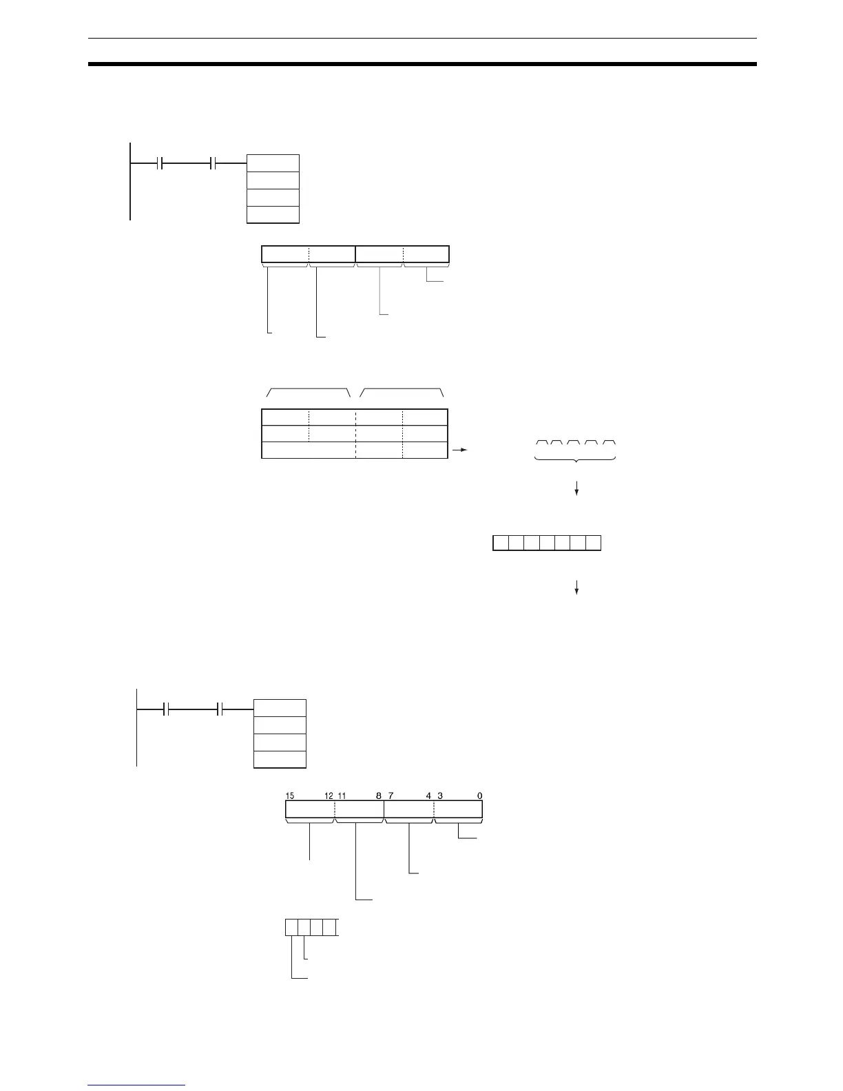
Example: Performing
Signal Control
When CIO 0.01 and the Serial Port 1 Send Ready Flag (A392.13) are ON in
the following example, the RS signal is set according to the status of D300 bit
15 and the ER signal is set according to the status of D300 bit 14.
TXD
D100
D200
&0
0.01
S
C
N
A392.13
01C: D200
812 3415 0711
S: D100
D101
D102
015
3412
CDAB
EF
87
1 2 3 4 A B C D E F
ST 12 34 AB CD EF ED
Sent
ST: Start code (e.g., 02 hex)
ED: End code (e.g., 03 hex)
Start and end codes added according to set-
ting in PLC Setup (this example assumes
that both a start and end code have been
5 bytes
Sent in
specified
order.
Most signifi-
cant bytes
Least signif-
icant bytes
Byte order
0 hex: Most significant byte to least significant byte
RS and ER signal control
0 hex: RS and ER not controlled
Serial Port 1 Send
Ready Flag
Always 0
Serial port specifier
1 hex: Serial port 1
C: D400
S: D300
3
0
1 0 0 0
15 14 13 12
01
RS and ER signal control
3: RS and ER signal control.
ER signal set to 0
RS signal set to 1
TXD
D300
D400
&0
S
C
N
0.01 A392.13
Serial Port 1 Send
Ready Flag
Byte order
0: Most significant byte to least significant byte
Always 0
Serial port specifier
1: Serial Port 1 (i.e., Serial Communications Option Board
mounted in option slot 1)