835
Serial Communications Instructions Section 3-23
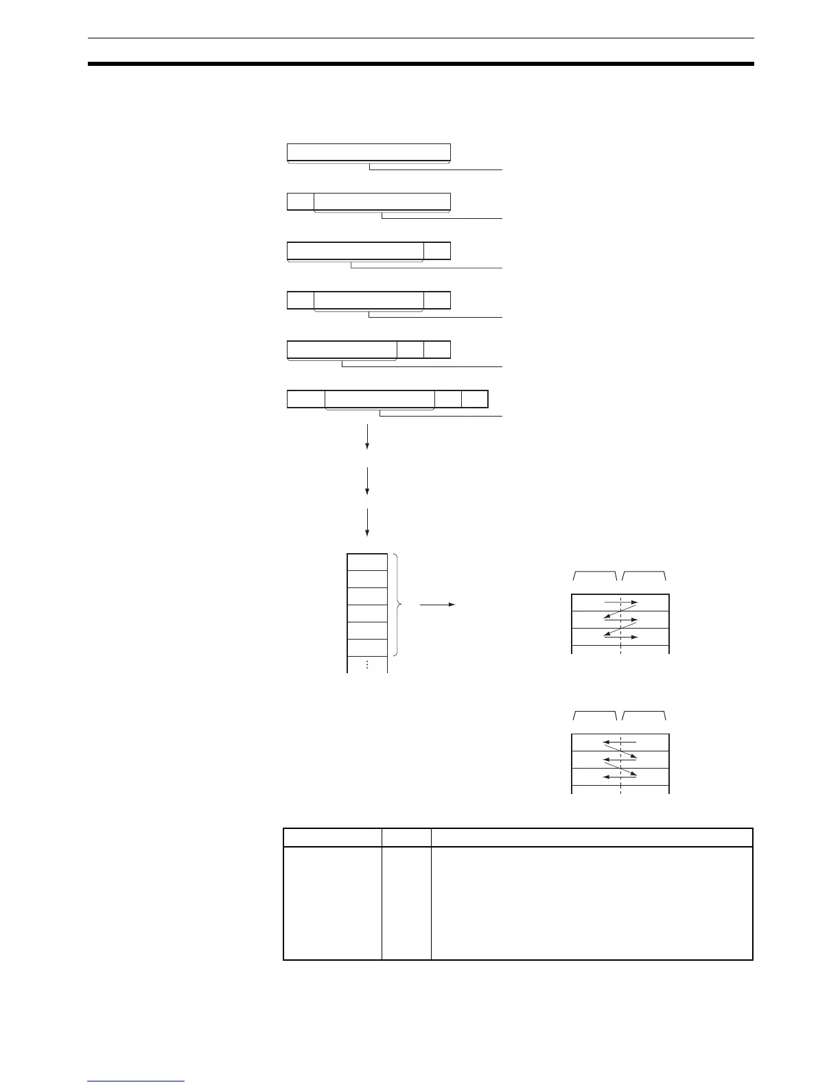
The following diagram shows the order in which data is sent and the contents
of the send frame for various start and end code settings.
Flags
ED
ST
ED
ST
CR
LF
ST
CR
LF
D
D+1
D+2
15 7 08
D
D+1
D+2
15 7 08
1
2
3
4
5
6
1
3
5
2
4
6
1
3
5
2
4
6
CR+LF End Code
Only End Code
Data
Data
Data
Data
Data
Data
No Start or End Code
Number of bytes
(Specified in allocated
DM Setup Area)
Only Start Code
Number of bytes up to ED:
256 max.
Start and End Code
Number of bytes between
ST and ED: 256 max.
Number of bytes up to
CR+LF: 256 max.
Number of bytes between
ST and CR+LF: 256 max.
Start and CR+LF End Code
Serial port on Serial Communications Unit
Data received.
Number of bytes
(Specified in allocated
DM Setup Area)
Bytes
N Storage order
(256 bytes max.)
Most signifi-
cant bytes
Least signif-
icant bytes
Byte order
0: Most significant bytes first
Most signifi-
cant bytes
Least signif-
icant bytes
Byte order
1: Least significant bytes first
Name Label Operation
Error Flag ER ON if all of the logical ports are being used or the Com-
munications Port Enabled Flag (A202.00 to A202.07) for
the specified logical port is OFF when the instruction is
executed.
ON if the value of C is not within range.
ON if the value for N is not between 0000 and 0100 hex.
OFF in all other cases.