847
Network Instructions Section 3-24
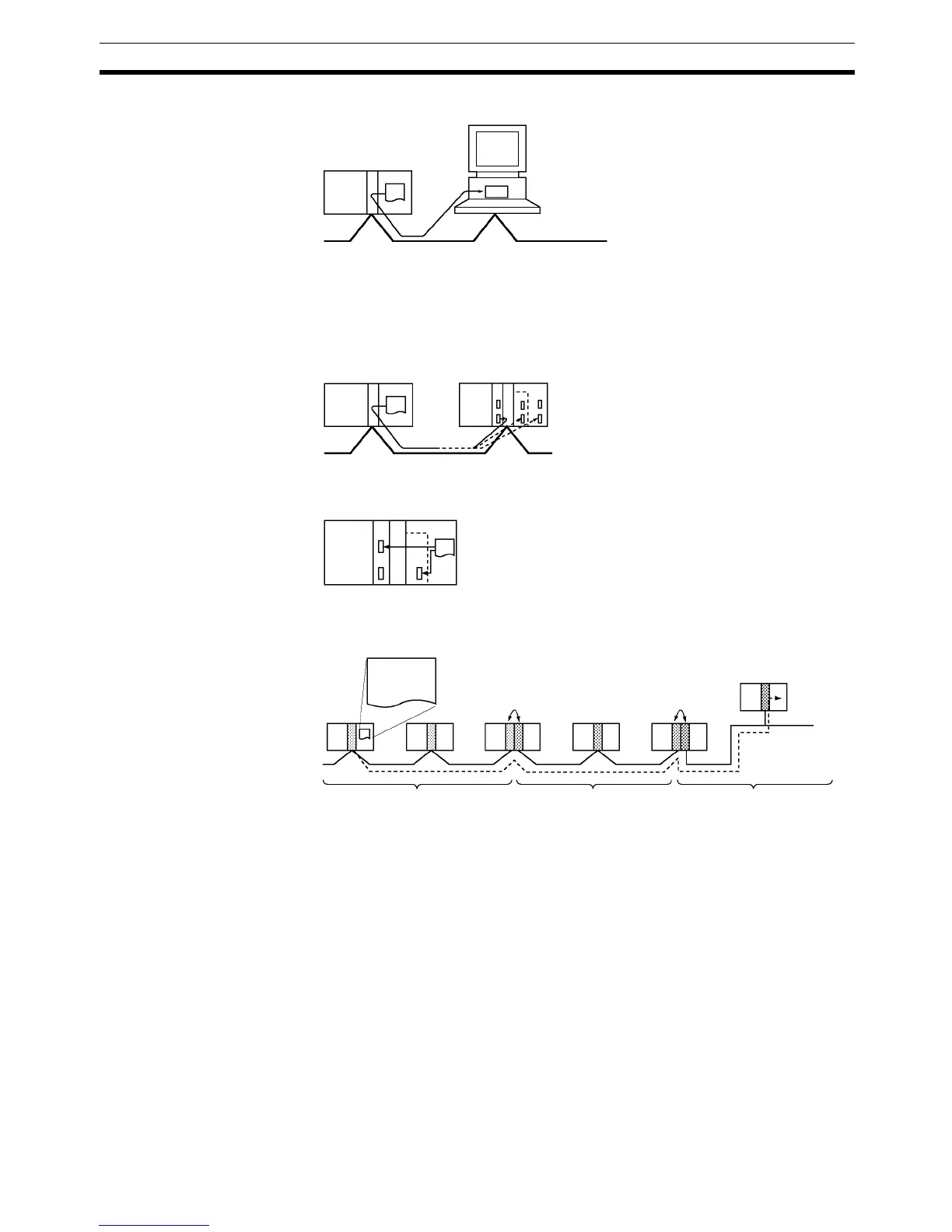
This example shows communications from a PLC to a personal computer.
Communications to a Serial Port in the Network
These examples show communications from a PLC to serial ports in devices
in the network. The first shows communications to serial ports in devices in
another PLC (the CPU Unit, CPU Bus Unit, or Inner Board) and the second
shows communications to a serial port within the CPU Rack itself.
Note Communications can span up to 8 network levels, including the local network.
(The local network is the network where the communications originate.)
In order to communicate through the network, it is necessary to register a
routing table in each PLC’s CPU Unit which indicates the route by which data
will be transferred to the desired node. Each routing table is made up of a
local network table and a relay network table.
1,2,3... 1. Local network table
This table shows the unit numbers and network addresses of the nodes
connected to the local PLC.
2. Relay network table
This table shows the node numbers and network addresses of the first re-
lay nodes to destination networks that are not connected to the local PLC.
PLC to computer
Through the network
Within the CPU Rack
Network 1
(local network)
Network 2
Network 3
Bridge or gatewayBridge or gateway
SEND(090),
RECV(098), or
CMND(490)